Multi-port cabling system and method

a multi-port cabling and multi-port technology, applied in the direction of coupling device details, electrical discharge lamps, coupling device connections, etc., can solve the problems of affecting the installation efficiency so as to facilitate the wall-mounting of the cabling system, increase or decrease the number of installed ports, and facilitate the effect of easy and rapid deploymen

Inactive Publication Date: 2009-06-04
AMERICA POWER CONVERSION CORP
View PDF44 Cites 11 Cited by
  • Summary
  • Abstract
  • Description
  • Claims
  • Application Information

AI Technical Summary

Benefits of technology

[0016]Various aspects of the invention may provide one or more of the following capabilities. Cable installation to equipment racks and rack enclosures can be organized such that the number of cables needed to meet service requirements is reduced. A reduced number of cables requires fewer components for installation and management and thereby can help to reduce the need for cable trays and wire management components and hardware. As a result, cable installation can be faster with reduced labor, which often translates into lower installation costs. In addition, a reduced number of cables can help to reduce or eliminate disturbance to active equipment operating in an equipment room or data center during installation. The reduced number of cables can help to minimize the amount of intra-rack and inter-rack space required for cabling and cable management. Further, the reduced number of cables helps to decrease the diameter of, for instance, a cable bundle such that cables can be easily routed in a rack or a cable tray.
[0026]A plurality of connector heads can provide scalability and flexibility for future expansion by enabling a plurality of ports to be readily deployed within racks or enclosures such that spare ports are available with reduced installation effort and at reduced cost. In addition, an expandable design provided by a plurality of connector heads of the cabling system can reduce downtime of equipment and data centers during reconfiguration and expansion.

Problems solved by technology

Configuration of equipment rooms and data and network centers to create effective IT environments presents a number of challenges.
Such patch panels can have a massive number of cables such that installing and managing these cables is a significant task.
Wire termination to punch down blocks requires a technician and is time-consuming, often contributing substantially to installation costs.
Patch panel cable installations are typically considered “built-in” and are essentially permanent configurations as relocating such installations, for instance, during reconfiguration of racks or equipment rooms is often inconvenient and difficult.

Method used


Image

  • Multi-port cabling system and method
  • Multi-port cabling system and method
  • Multi-port cabling system and method

Examples


Embodiment Construction

[0055]This invention is not limited in its application to the details of construction and the arrangement of components set forth in the following description or illustrated in the drawings. The invention is capable of other embodiments and of being practiced or of being carried out in various ways. Also, the phraseology and terminology used herein is for the purpose of description and should not be regarded as limiting. The use of “including,”“comprising,” or “having,”“containing,”“involving” and variations thereof herein, is meant to encompass the items listed thereafter and equivalents thereof as well as additional items.

DETAILED DESCRIPTION OF PREFERRED EMBODIMENTS

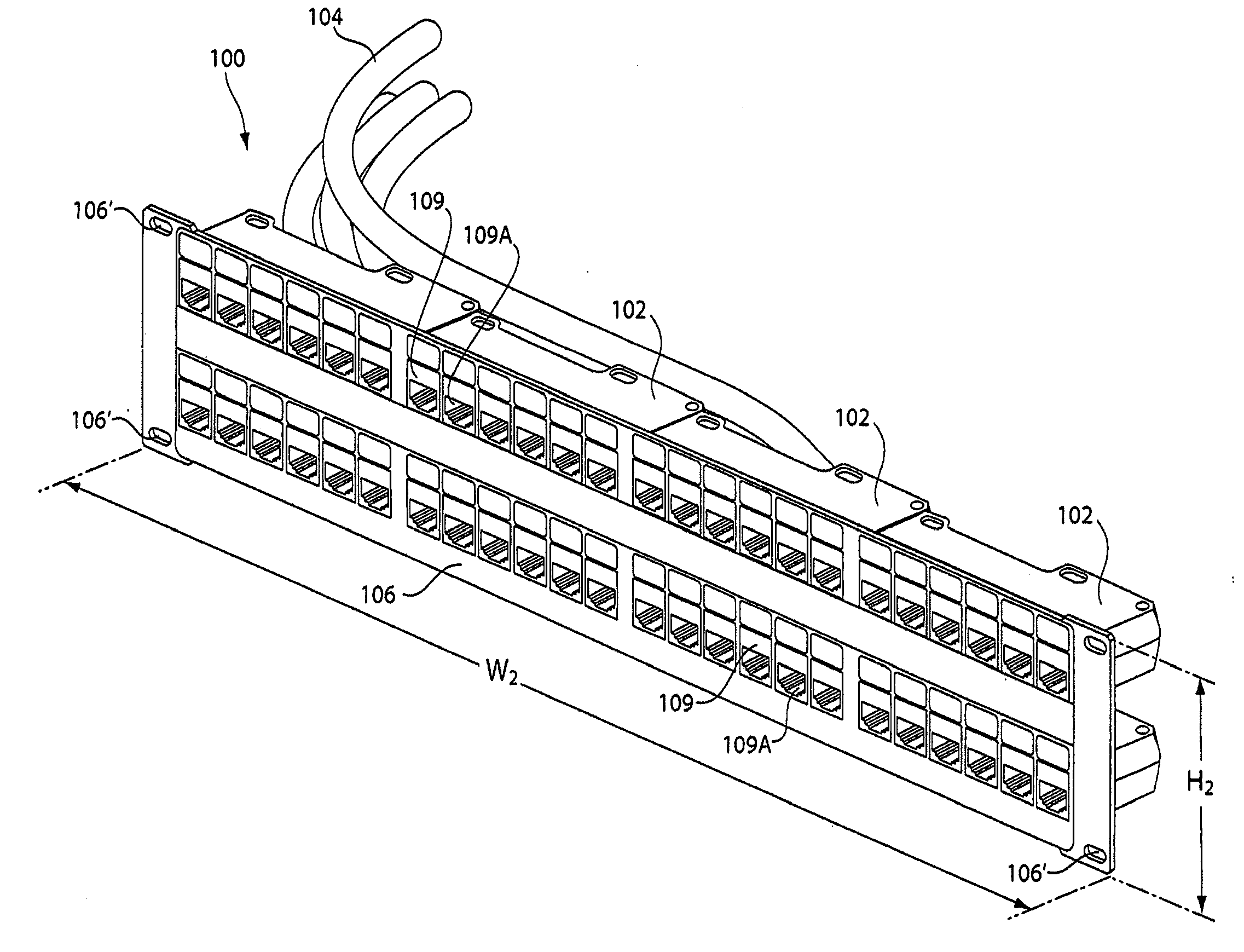
[0056]The invention provides a cabling system configured for use in rack enclosures and open-frame racks employed in server, telecommunications and networking applications to configure IT environments of equipment rooms, data centers and networking centers. The cabling system according to the invention is configured to...


PUM


Abstract

A multi-port cabling system for use in installing cable to an equipment rack or enclosure or within an equipment room or data center includes a cabling assembly comprising at least one connector head having a plurality of ports and at least one cable operatively connected to the plurality of ports. The at least one cable terminates internally within the connector head to operatively couple the cable to the plurality of ports. The system further includes a mounting bracket. The mounting bracket and the connector head are each configured for tool-less attachment of one or more cabling assemblies to the bracket. The mounting bracket is further configured to removably mount to an equipment rack or enclosure, and / or to a wall, to thereby install one or more cables. The cabling assembly and the cabling system help to eliminate on-site cable termination and testing during installation of cables to rack-mounted equipment.

Description

RELATED APPLICATIONS[0001]This application claims the benefit under 35 U.S.C. § 120 of U.S. application Ser. No. 10 / 901,460, entitled “MULTI-PORT CABLING SYSTEM AND METHOD,” filed on Jul. 28, 2004, which is herein incorporated by reference in its entirety.BACKGROUND OF INVENTION[0002]1. Field of Invention[0003]The invention relates to cable installation and management in an equipment rack or enclosure.[0004]2. Discussion of Related Art[0005]Configuration of equipment rooms and data and network centers to create effective IT environments presents a number of challenges. Integration of servers, networking equipment and storage devices, for instance, requires careful planning to configure an environment that can address current as well as future and varying requirements. Such requirements can include signal speeds, power densities, cooling and flexibility with respect to rack equipment architecture. Ideal solutions to meet such requirements are quick and easy to install such that new c...

Claims


Application Information

Patent Timeline
Patent Type & Authority Applications(United States)
IPC IPC(8): H01R33/00
CPCH01R13/741H01R25/003H04Q1/141Y10T29/49208H04Q1/021H04Q1/13H04Q2201/02
Inventor SPITAELS, JAMES S.BRYAN, DANIEL
Owner AMERICA POWER CONVERSION CORP
Why Eureka
Try Eureka