

Pointer
Patent Information
- Authority / Receiving Office
- US · United States
- Current Assignee / Owner
- YAZAKI CORP
- Publication Date
- 2006-02-23
Smart Images
Figure 1 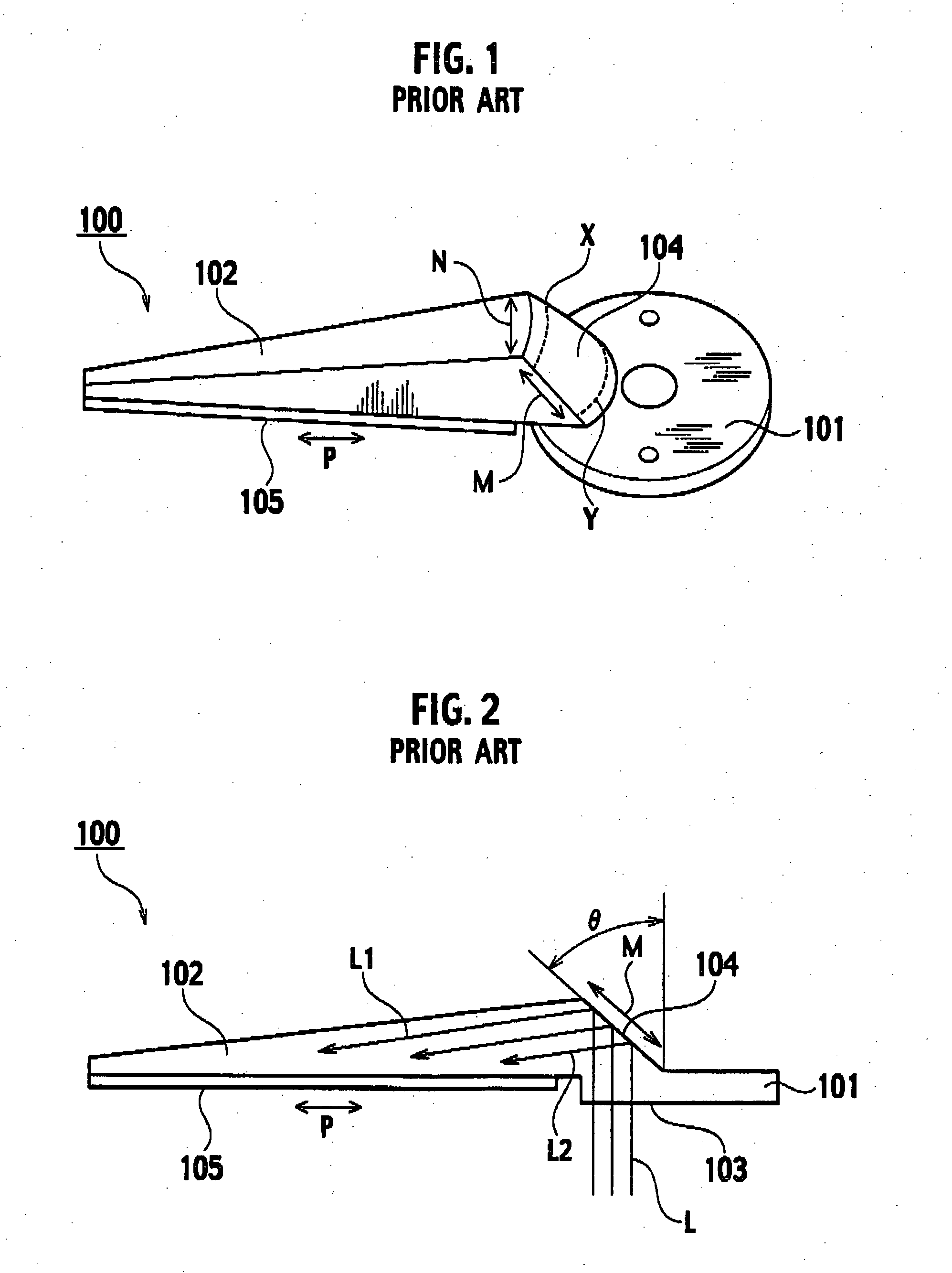
Figure 2 
Figure 3
Abstract
Description
CROSS REFERENCE TO RELATED APPLICATION
[0001] This application claims benefit of priority under 35 U.S.C. §119 to Japanese Patent Application No. 2004-238188, filed on Aug. 18, 2004, the entire contents of which are incorporated by reference herein. BACKGROUND OF THE INVENTION
[0002] 1. Field of the Invention
[0003] The present invention relates to a pointer that employed in an instrument which is mounted on a vehicle, an airplane, a ship etc.
[0004] 2. Description of the Related Art
[0005] A self-luminous pointer is widely used as a pointer employed in an instrument. A conventional self-luminous pointer is disclosed in Japanese Unexamined Patent Publication No. H11-194040.
[0006] As shown in FIG. 1, a pointer 100 comprises an attached portion 101 and a tapered main body 102. The attached portion 101 is attached to a rotary shaft of an instrument (not shown). The main body 102 is fixed to the attached portion 101 at a basic portion thereof and extends toward a free portion thereof. ...