Pointer having a curved Reflective Surface

a reflective surface and pointer technology, applied in the field of pointers, can solve problems such as poor handling, and achieve the effect of easy and efficient lightening

Active Publication Date: 2009-12-22
YAZAKI CORP
View PDF22 Cites 5 Cited by
  • Summary
  • Abstract
  • Description
  • Claims
  • Application Information

AI Technical Summary

Benefits of technology

[0012]The object of the present invention is to provide a pointer configured to be easily and efficiently lightened by light emitted from a light source without generating uneven light strength therein.

Problems solved by technology

This leads to a poor handling.

Method used


Image

  • Pointer having a curved Reflective Surface
  • Pointer having a curved Reflective Surface
  • Pointer having a curved Reflective Surface

Examples


Embodiment Construction

[0037]Hereinafter, with reference to FIGS. 5 to 10, an embodiment of the present invention will be described.

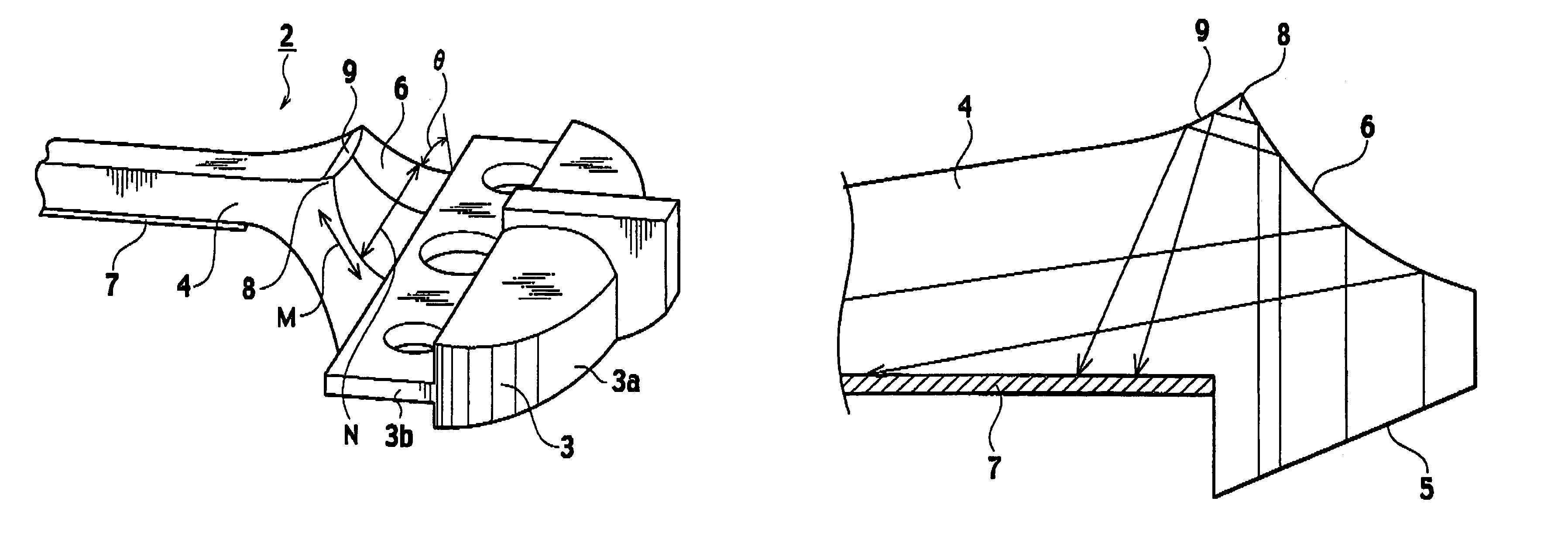
[0038]As shown in FIGS. 5 and 6, a pointer cap 1 has a screw portion 1a and a column-shaped housing 1b. The screw portion 1a is fixed to an upper end of the housing 1b and projects downward from the housing 1b. The pointer cap 1 is fixed to a drive shaft of an instrument (not shown) by means of the screw portion 1a.

[0039]A pointer 2 rotates with the pointer cap 1 around the screw portion 1a by a rotation of the drive shaft. The pointer 2 comprises an attached portion 3 and a tapered main body 4.

[0040]The housing 1b accommodates the attached portion 3. As shown in FIG. 7, the attached portion 3 has a half-column region 3a and a plane region 3b. The half-column region 3a is fixed to the plane region 3b at a side face thereof. The plane region 3b has a right hole, a left hole and a central hole. The screw portion 1a is inserted into the central hole (see FIG. 6). Thereby, the a...


PUM


Abstract

A pointer comprises an attached portion and a main body. The attached portion is attached to an instrument. The main body is fixed to the attached portion at a basic portion thereof and extending toward a free portion thereof. The main body has a reflective surface and a foil-stamping layer. The reflective surface is formed at an inclined surface of the basic portion and inclined to a traveling direction of light entering the main body. The foil-stamping layer is formed on a bottom surface of the main body and diffusely reflects light reflected by the reflective surface. The reflective surface is curved like a collective convex lens in a transverse direction of the inclined surface and a diffusive concave lens in a vertical direction of the inclined surface.

Description

CROSS REFERENCE TO RELATED APPLICATION[0001]This application claims benefit of priority under 35 U.S.C. § 119 to Japanese Patent Application No. 2004-238188, filed on Aug. 18, 2004, the entire contents of which are incorporated by reference herein.BACKGROUND OF THE INVENTION[0002]1. Field of the Invention[0003]The present invention relates to a pointer that is employed in an instrument which is mounted on a vehicle, an airplane, a ship, etc.[0004]2. Description of the Related Art[0005]A self-luminous pointer is widely used as a pointer employed in an instrument. A conventional self-luminous pointer is disclosed in Japanese Unexamined Patent Publication No. H11-194040.[0006]As shown in FIG. 1, a pointer 100 comprises an attached portion 101 and a tapered main body 102. The attached portion 101 is attached to a rotary shaft of an instrument (not shown). The main body 102 is fixed to the attached portion 101 at a basic portion thereof and extends toward a free portion thereof. The atta...

Claims


Application Information

Patent Timeline
Patent Type & Authority Patents(United States)
IPC IPC(8): G01D11/28
CPCB60K37/02G12B11/04G01D13/265B60K2350/1064B60K2350/203B60K2370/154B60K2370/33B60K2370/6992
Inventor TAKATSUKA, MOTOHIRONAKAMURA, MASAAKI
Owner YAZAKI CORP
Why Eureka
Try Eureka