Pop-up flash of a camera

a pop-up flash and camera technology, applied in the field of pop-up flashes of cameras, can solve the problems of increasing the dimensions of the camera, adversely affecting the camera design, and the dimensions of the pop-up flash and the space for the same are apt to be limited by the camera body, so as to prevent the effect of catching the flashlight and preventing vignetting

Active Publication Date: 2006-02-23
RICOH IMAGING COMPANY
View PDF9 Cites 3 Cited by
  • Summary
  • Abstract
  • Description
  • Claims
  • Application Information

AI Technical Summary

Benefits of technology

[0006] The present invention provides a pop-up flash of a camera which is constructed to be capable of effectively preventing flashlight from being intercepted by any part of the camera to thereby prevent vignetting from occurring in flash photography. The present invention provides such a pop-up flash, which can be manually retracted smoothly in an easy manner, is achieved.

Problems solved by technology

However, the dimensions of this type of pop-up flash and the space for the same are apt to be limited by the camera body.
Giving a higher priority to the optical performance of the flash may increase the dimensions of the camera and have an adverse influence on the camera design.

Method used


Image

  • Pop-up flash of a camera
  • Pop-up flash of a camera
  • Pop-up flash of a camera

Examples


Embodiment Construction

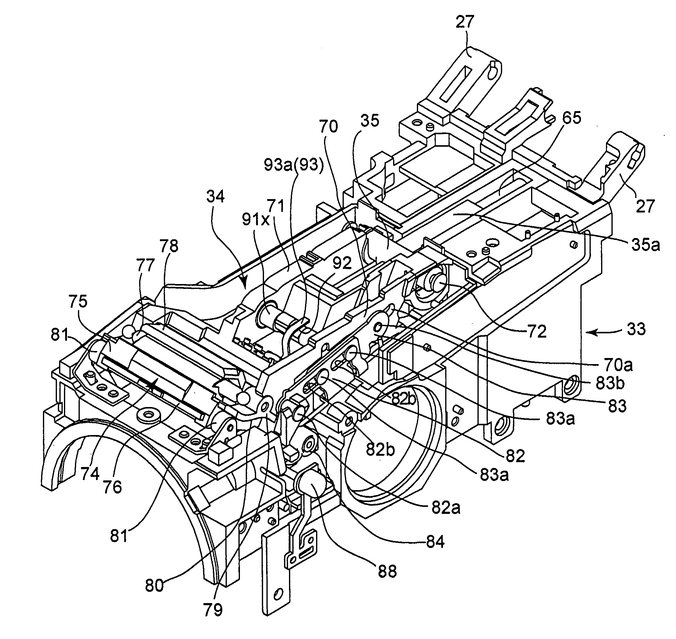
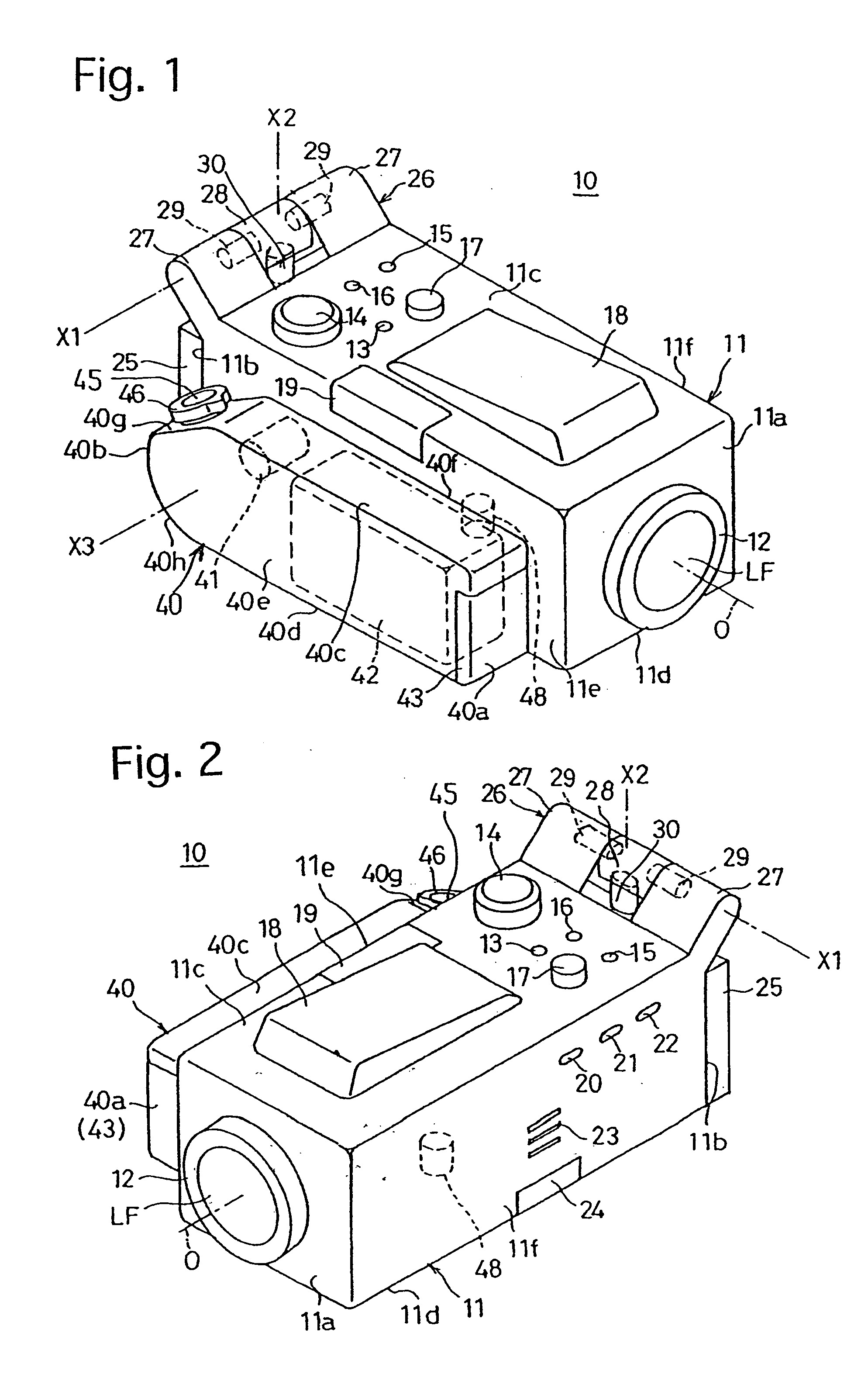
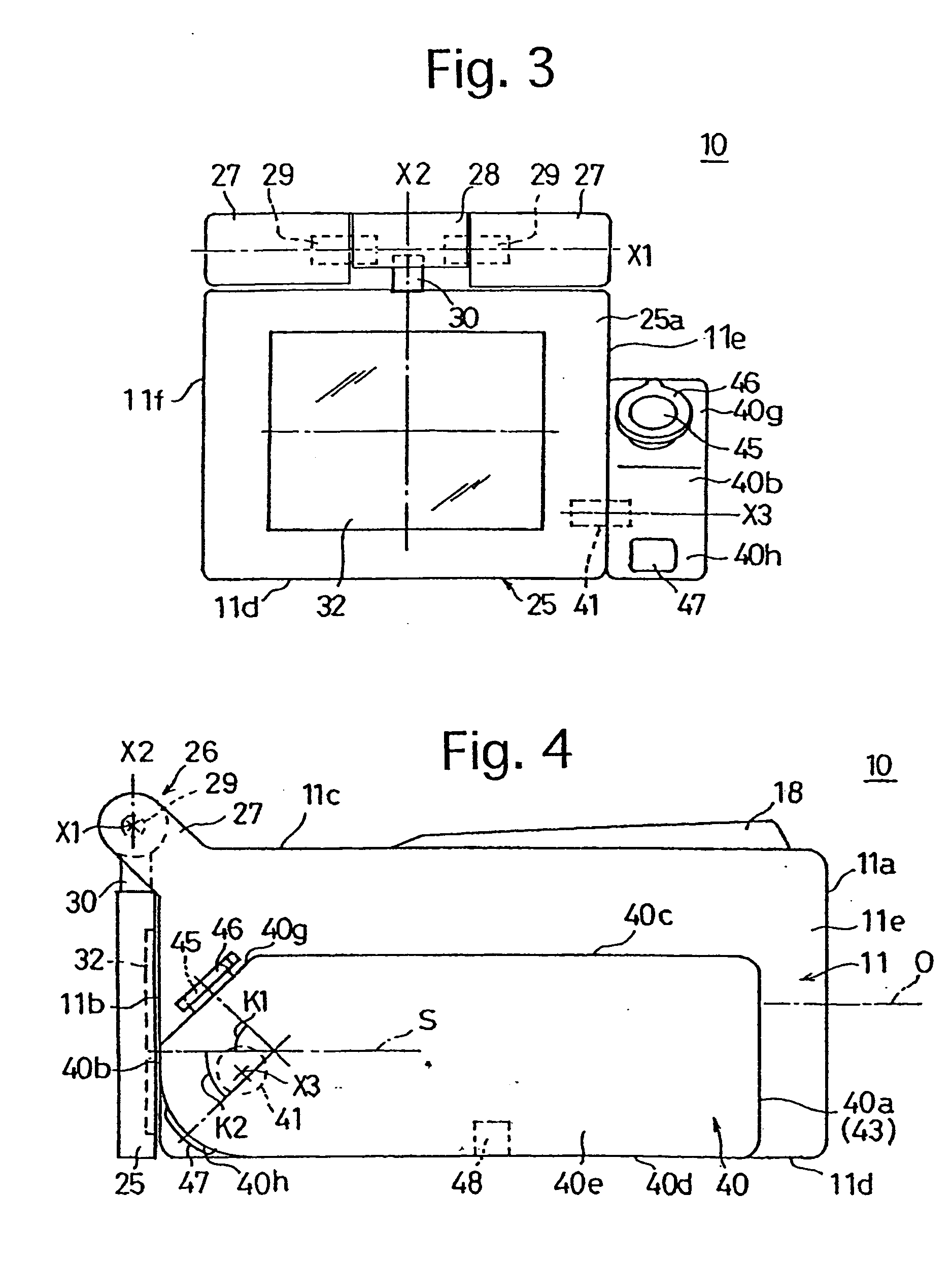
[0062]FIGS. 1 through 12 show an embodiment of a digital camera according to the present invention. This digital camera 10 is provided with a camera body 11 including a photographing optical system. The camera body 11 is formed in a substantially rectangular parallelepiped which is elongated along an optical axis O of the photographing optical system. The outer surface of the camera body 11 is composed of six surfaces: a front end surface 11a, a rear end surface 11b, a top surface 11c, a bottom surface 11d, a right side surface 11e and a left side surface 11f. The top surface 11c, the bottom surface 11d, the right side surface 11e and the left side surface 11f connect the front end surface 11a with the rear end surface 11b, and surround the optical axis O. In the present embodiment of the digital camera, the vertical direction and the horizontal direction of FIGS. 3, 11 and 12 corresponds to the vertical direction and the horizontal direction of the digital camera 10, respectively. ...


PUM


Abstract

A pop-up flash of a camera includes a slidable member mounted to a camera body, the slidable member being movable between a retreated position and an advanced position in front of the retreated position; and a flash unit supported by the slidable member to be movable between a retracted position, in which the flash unit is accommodated in the camera body, and a fully-lifted position in which the flash unit projects from the camera body. The flash unit moves from the retracted position to the fully-lifted position when the slidable member moves from the retreated position to the advanced position.

Description

BACKGROUND OF THE INVENTION [0001] 1. Field of the Invention [0002] The present invention relates to a pop-up flash of a camera which pops up out of a camera body in flash photography. [0003] 2. Description of the Related Art [0004] In general flash photography, the flashlight may be partly intercepted by a part of the camera which is positioned in front of a light emitting portion of the flash (e.g., a front edge of a lens barrel, a lens hood or a conversion lens) in a direction of the photographing optical axis to cause vignetting if the light emitting portion is positioned too closely to the photographing optical axis or the rear of the camera body. For instance, various types of cameras are equipped with a pop-up flash movable between a retracted position, in which the light emitting portion is retracted into a camera body, and a pop-up position (projection position / fully-lifted position), in which the light emitting portion projects from the camera body. However, the dimensions...

Claims


Application Information

Patent Timeline
Patent Type & Authority Applications(United States)
IPC IPC(8): G03B15/03
CPCG03B15/05G03B2215/0507
Inventor YAMADA, TOSHIAKI
Owner RICOH IMAGING COMPANY
Why Eureka
Try Eureka