High frequency oscilloscope probe with unitized probe tips

a technology of high frequency oscilloscope and probe tip, which is applied in the direction of electrical testing, measurement devices, instruments, etc., can solve the problems of loss of cable, limitations of this approach, and large size of probes, so as to minimize the loop area and reduce the size

Inactive Publication Date: 2006-03-23
DIGITAL GLOBAL SYST INC +1
View PDF13 Cites 31 Cited by
  • Summary
  • Abstract
  • Description
  • Claims
  • Application Information

AI Technical Summary

Benefits of technology

[0009] Probe tip assemblies for a micro-browser are reduced in size in a first embodiment by using small surface mount components in an isolation/coupling network that may include a parallel RC combination in series with a damping resistor. These surface mount components are soldered directly to one another without the use of a substrate. A pointed contact tip is soldered directly to one end of the surface mount components, and at the other end of those components is soldered the center conductor of a coaxial transmission line leading to a replication amplifier. A portion of the isolation/coupling network is enclosed within a supporting conductive shield that is also soldered to the outer conductive shield of the coaxial transmission line. The isolation/coupling network is supported against the coaxial cable's center conductor and its connection thereto strain relieved by potting the isolation/coupling network into the conductive shield. The result is a unitized probe tip assembly. A pair of unitized probe tip assemblies may be mechanically attached to a respective pair of s

Problems solved by technology

Beside the issue of the 'scope's frequency response, the main electrically troublesome issues with this arrangement are losses in the cable and the discontinuities presented by the RF connectors of the cable.
Unfortunately, more is generally demanded of a high performance wide-band DSO; it is often desired to probe locations within circuitry that neither expects nor tolerates a terminating load.
The limitations of this approach soon become apparent as signal frequencies get even higher, and active probes became common.
It results, however, in a rather bulky probe that often cannot be physically deployed where its services are needed because of the

Method used


Image

  • High frequency oscilloscope probe with unitized probe tips
  • High frequency oscilloscope probe with unitized probe tips
  • High frequency oscilloscope probe with unitized probe tips

Examples


Embodiment Construction

[0023] The following is an abridged version of the description of FIGS. 1-3 from the incorporated UNBREAKABLE MICRO-BROWSER. We include it here to set forth the immediate environment into which we shall introduce and describe the invention.

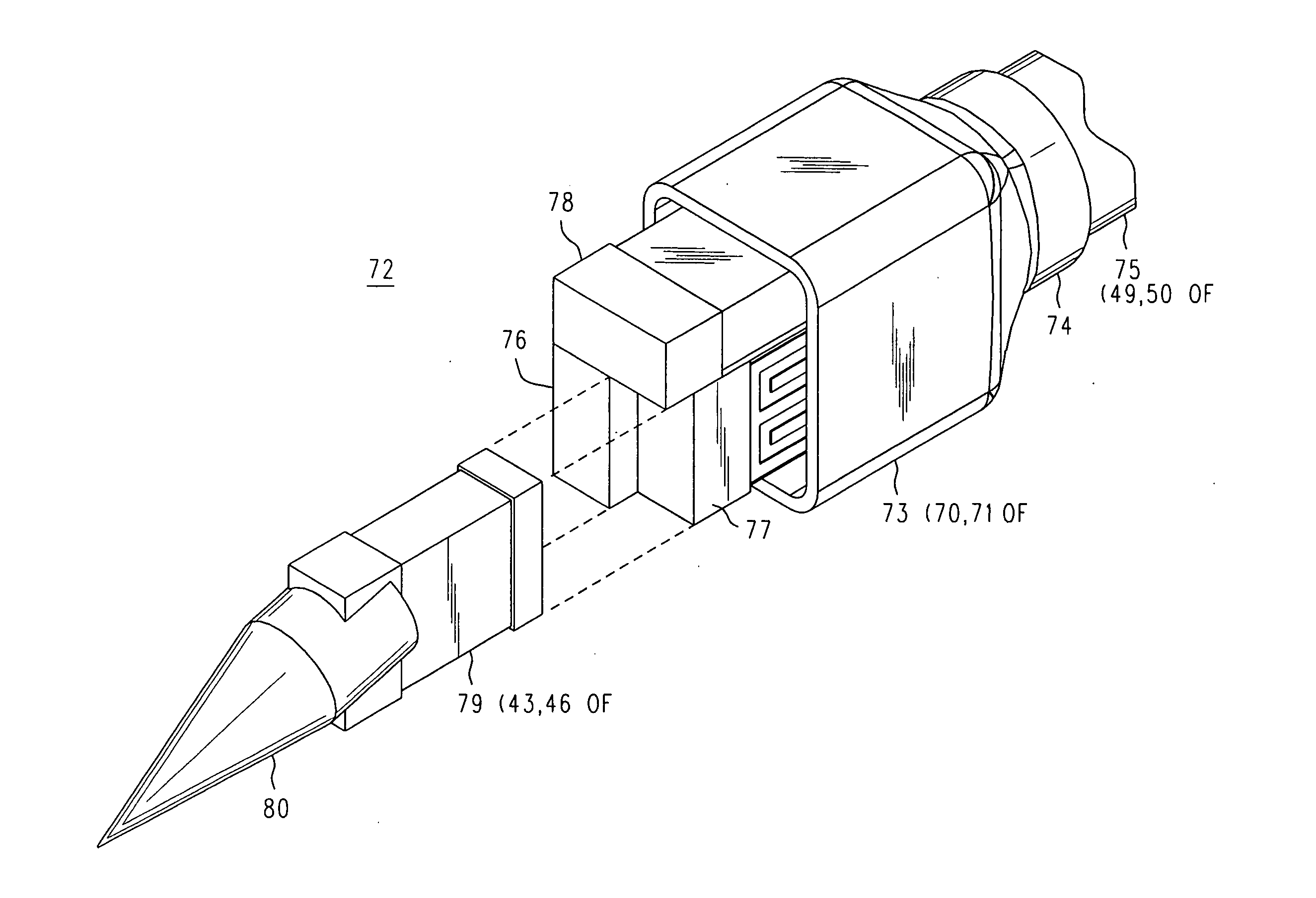
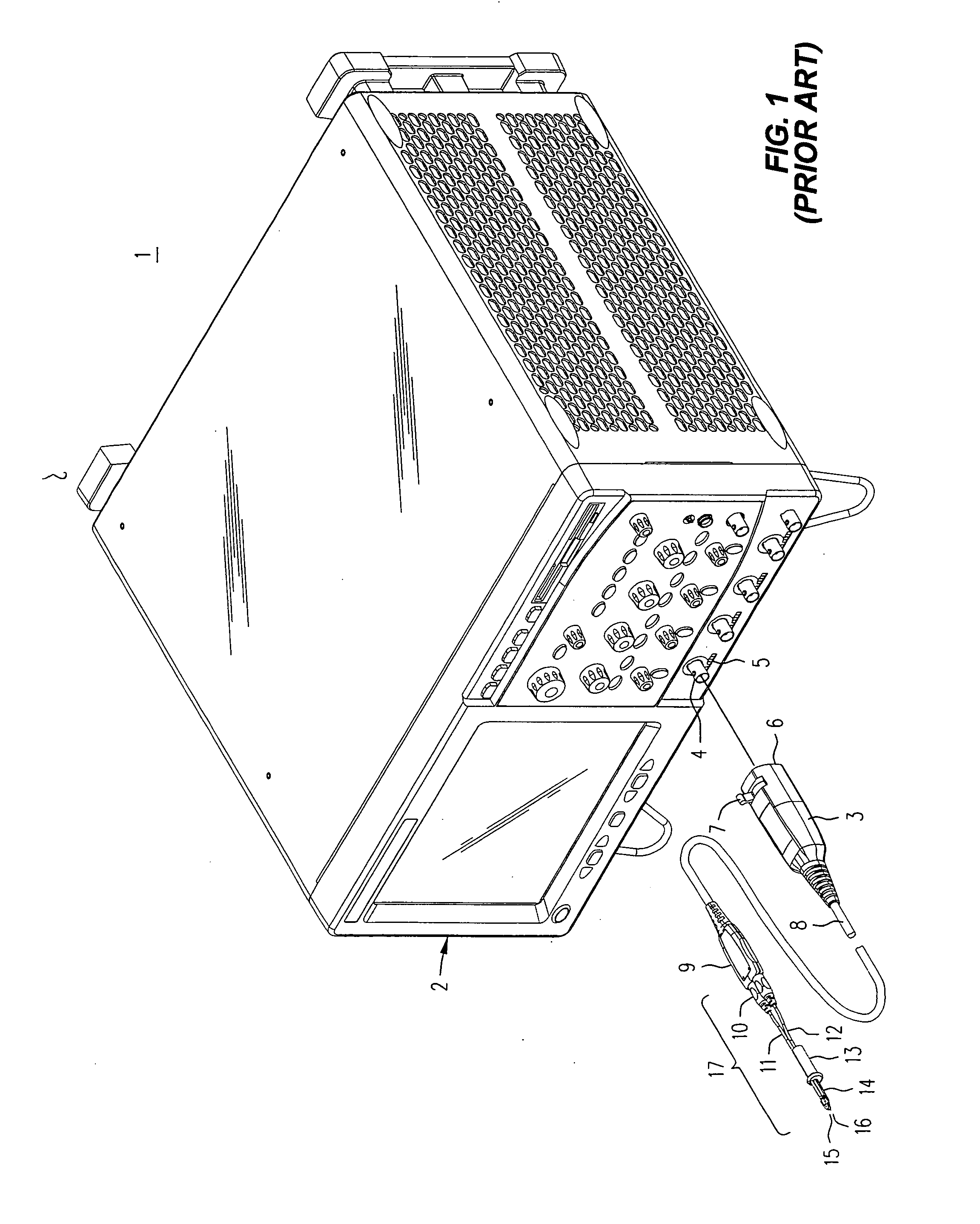
[0024] Refer now to FIG. 1, wherein is shown a front perspective view of an electronic instrument 2, such as a digital oscilloscope, having one or more front panel connectors 4 that each receive a push-lock BNC connector 3, say, in support of operation with active probes. In a manner known in the prior art, the push-lock BNC probe housing is installed simply by lining it up and then pushing it toward the 'scope. When the push-lock connector 3 is in place, not only is a BNC connection established to connector 4, but a row of spring loaded pins 6 (not visible) on the front panel of the housing for the push-lock assembly engages a row 5 of contacts beneath the connector 4. To remove the push-lock connector the operator pushes on lever or tab 7 with ...


PUM


Abstract

Unitized probe tip assemblies of reduced size for a micro-browser use surface mount components in an isolation/coupling network that may include a parallel RC combination in series with a damping resistor. These surface mount components are soldered directly to one another without the use of a substrate. A pointed contact tip is soldered directly to one end of the surface mount components, and at the other end of those components is soldered the center conductor of a coaxial transmission line leading to a replication amplifier. A portion of the isolation/coupling network is enclosed within a supporting conductive shield that is also soldered to the outer conductive shield of the coaxial cable, which may be a semi-rigid micro coax (which might also be of a memory metal, such as Nitinol) that transitions into a flexible coaxial cable after leaving a slot in a sleeve that carries stationary and rotating rods (which might also be of a memory metal) to which the unitized probe tip assemblies are attached. In an alternate embodiment the isolation/coupling network may be a shaft of resistive diamond having a sharp tip at one end where it has a low bulk resistance the functions as a series damping resistance, which shaft also has toward the other end a much higher bulk resistance that functions as an isolation resistance that is also shunted by a coupling capacitance formed of a conductive pattern printed on the outside of the region of higher bulk resistance.

Description

REFERENCE TO RELATED APPLICATIONS [0001] This application is related to other developments in the field of high frequency probes. As is well known and appreciated, the “mechanical” aspect of high frequency structures often have a significant effect on their electrical performance, so that sometimes it is somewhat artificial to describe certain important probe properties as “mechanical” and others as “electrical.” That said, it is not insensible to think of some outcomes as having been produced primarily through choices of physical parameters in three dimensions (“mechanical”), as opposed to circuit values for components in a schematic (“electrical”). For the sake of brevity concerning mechanical developments, U.S. patent application Ser. No. 10 / 829,725 entitled COMPLIANT MICRO-BROWSER FOR A HAND HELD PROBE filed 22 April by James E. Cannon, et al., and U.S. patent application Ser. No. 10 / 834,549 entitled UNBREAKABLE MICRO-BROWSER filed 28 Apr. 2004 by James E. Cannon are each hereby...

Claims


Application Information

Patent Timeline
IPC IPC(8): G01R31/02
CPCG01R1/06788G01R1/06772
Inventor CANNON, JAMES E.MCTIGUE, MICHAEL T.
Owner DIGITAL GLOBAL SYST INC
Why Eureka
Try Eureka