AI technical title is built by Patsnap AI team. It summarizes the technical point description of the patent document.
a technology of energized segmented rings and latches, which is applied in the direction of fastening means, couplings, manufacturing tools, etc., can solve problems such as spring damag
Inactive Publication Date: 2006-04-20
BAL SEAL ENG CO INC
View PDF16 Cites 21 Cited by
Summary
Abstract
Description
Claims
Application Information
AI Technical Summary
This helps you quickly interpret patents by identifying the three key elements:
Problems solved by technology
Method used
Benefits of technology
Problems solved by technology
Latching devices such as those set forth in U.S. Pat. Nos. 4,804,290, 5,082,390, and 6,749,358 to Balsells typically utilize springs wherein the spring is in direct contact with a shaft, however continued use of such latches may cause spring damage.
Method used
Image
Click on the blue label to locate the original text in one second.
Reading with bidirectional positioning of images and text.
Examples
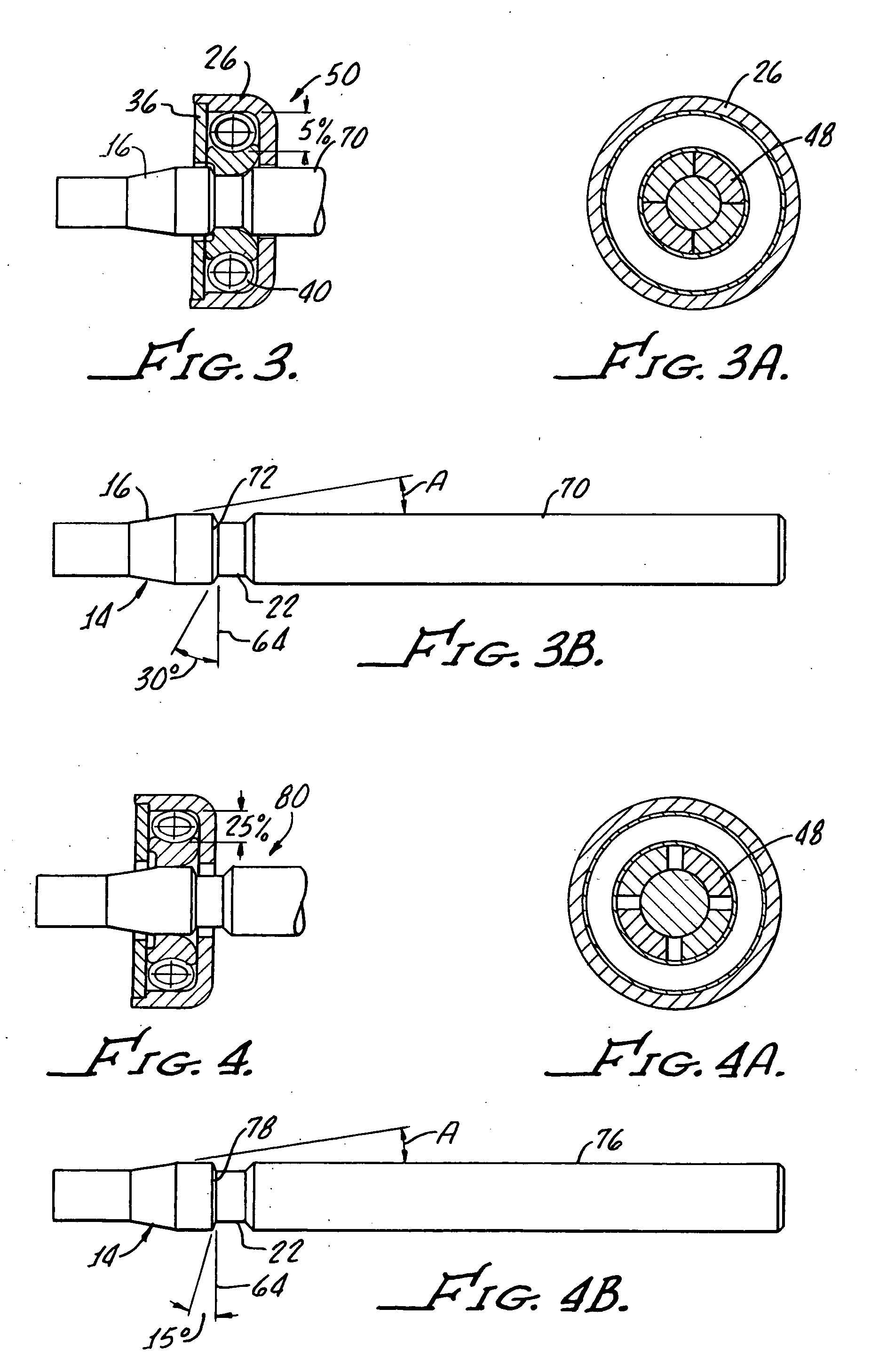
embodiment 50
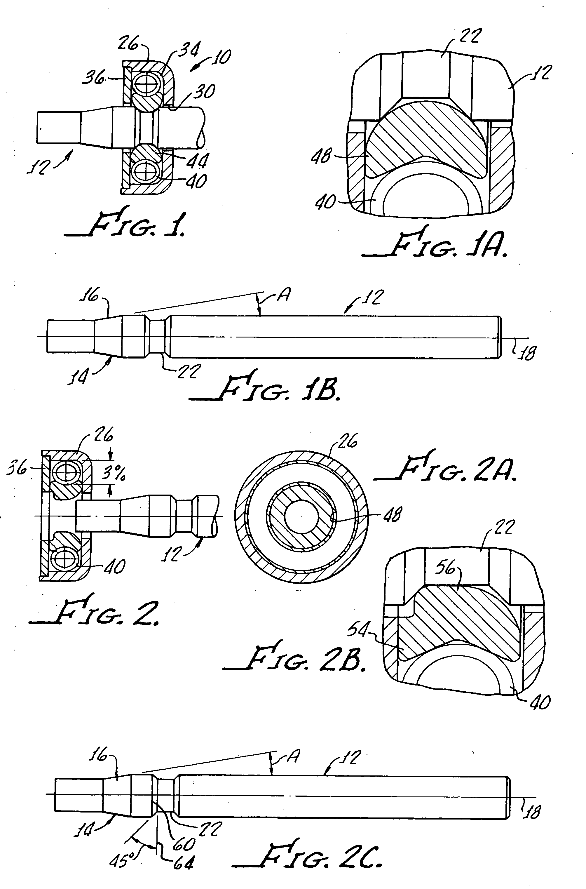
[0052]FIGS. 3, 3A, and 3B, illustrate the embodiment 50 of the device in accordance with the present invention with a shaft 70 having a shoulder 72 at a 30° angle to a normal 64, which provides a connect / disconnect of about 1 to 6. In this embodiment, the spring 40 is shown with a 5° deflection and FIG. 3A illustrates the dogs 48 interconnected position with the groove 22.
embodiment 80
[0053] The embodiment 80 shown in FIGS. 4, 4A, 4B is similar to that as shown in FIGS. 3-3B with a spring deflection of about 25% with a shaft 76 having a shoulder 78 at a 15° angle to the normal 64 which provides for a connect / disconnect ratio of about 1 / 10.
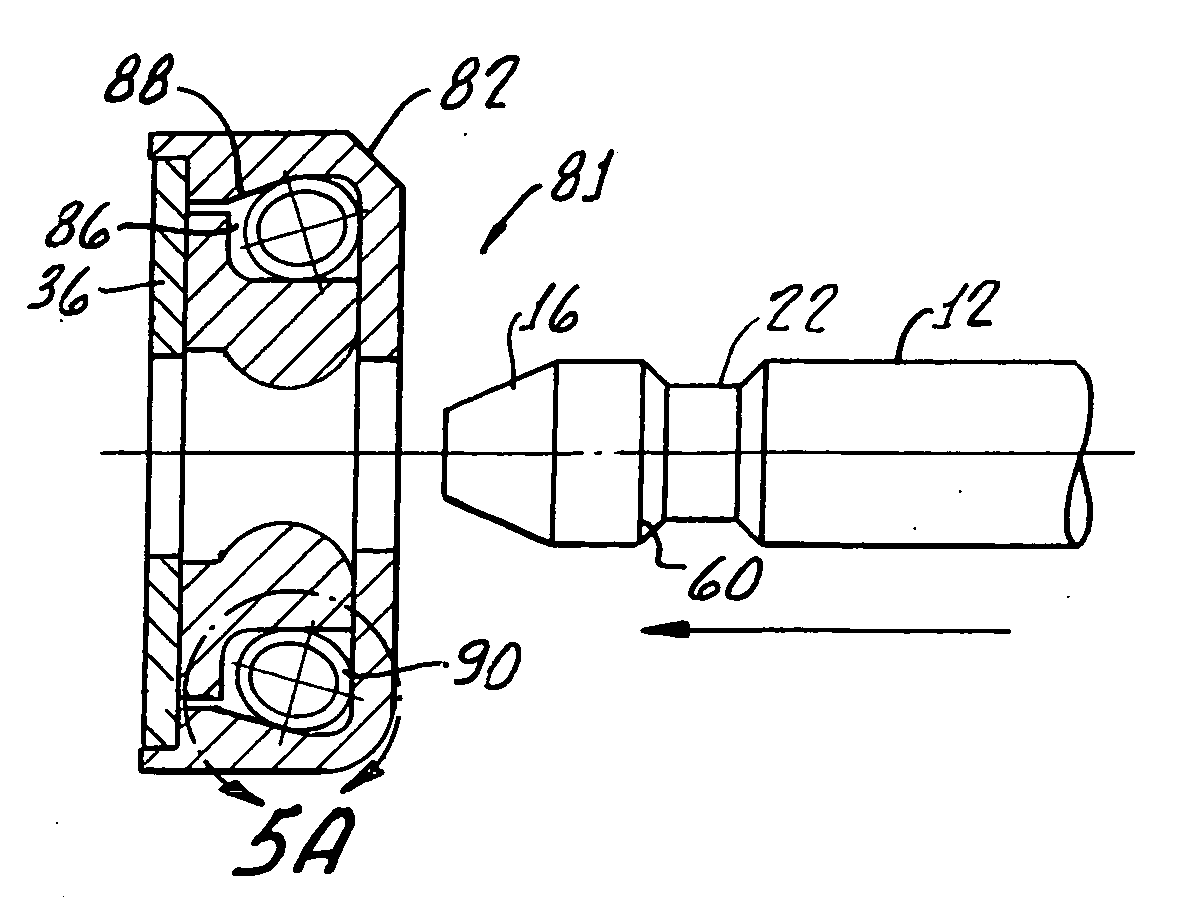
[0054]FIGS. 5, 5A, 5B illustrate yet another embodiment 81 in accordance with the present invention which includes a housing 82 in which the cavity 86 is angular, that is, having an angulated, or sloped, surface 88 and the spring 90 is disposed at an angle 94 with an axis 96.
[0055] With reference to FIGS. 6 and 6A, there is shown another embodiment of the device 100 in accordance with the present invention, common reference numbers indicating identical or substantially similar components to those earlier hereinabove described.
[0056] In this embodiment, a cantilever spring 102 is utilized for biasing the dogs 48 of the segmented ring 44.
[0057]FIGS. 7, 7A, 7B show yet another device 106 in accordance with the present invention ...
embodiment 114
[0058] With reference to FIGS. 8, 8A, 8B, there is shown an embodiment 114 utilizing either a helical extension spring 116. FIGS. 9, 9A show a canted extension spring 118 for biasing dogs 122, 124.
PUM
Abstract
A latch device includes a shaft having a surface of revolution defining an insertion surface disposed at an insertion angle along with a circumferential groove. A housing is provided which includes a shaft receiving bore therethrough and a torroidal cavity with a spring disposed therein. A segmented ring is provided which includes a plurality of separate sound producing dogs circumferentially disposed about the housing bore for latching between the housing and the shaft.
Description
[0001] The present application claims priority from U.S. Ser. No. 60 / 618,043 which is incorporated herewith in its entirety by this specific reference thereto.[0002] The present invention is generally related to latching devices and is more particularly directed to applications that require positive latching with both audio and tactile confirmation of the latch engagement and consistent bi-directional connect / disconnect forces. [0003] For many applications in the medical field, a latching device that has both audible and tactile confirmation of positive latching is very desirable. Many latching devices do not require any type of tool to provide for a secure latch between components. Latching devices such as those set forth in U.S. Pat. Nos. 4,804,290, 5,082,390, and 6,749,358 to Balsells typically utilize springs wherein the spring is in direct contact with a shaft, however continued use of such latches may cause spring damage. [0004] The present invention utilizes a segmented-ring ...
Claims
Application Information
Patent Timeline
Application Date:The date an application was filed.
Publication Date:The date a patent or application was officially published.
First Publication Date:The earliest publication date of a patent with the same application number.
Issue Date:Publication date of the patent grant document.
PCT Entry Date:The Entry date of PCT National Phase.
Estimated Expiry Date:The statutory expiry date of a patent right according to the Patent Law, and it is the longest term of protection that the patent right can achieve without the termination of the patent right due to other reasons(Term extension factor has been taken into account ).
Invalid Date:Actual expiry date is based on effective date or publication date of legal transaction data of invalid patent.
Patent Type & AuthorityApplications(United States)

