Biochemical reaction cartridge and biochemical treatment equipment system

a biochemical and reaction cartridge technology, applied in the direction of analytical instruments, laboratory glassware, chemical indicators, etc., can solve the problems of inaccurate probe detection, inability to perform accurate detection, and reduced apparent strength of detection light, so as to prevent the progression of deterioration of fluorescent dyes, accurate probe detection, and elimination of contamination of sites

Active Publication Date: 2006-05-04
CANON KK
View PDF7 Cites 23 Cited by
  • Summary
  • Abstract
  • Description
  • Claims
  • Application Information

AI Technical Summary

Benefits of technology

[0020] The present invention has significantly reduced or completely eliminated the possibility that an examiner unintentionally touches a site of a biochemical reaction cartridge required for probe detection or other sites functionally required for the cartridge during the handling of the cartridge and the possibility of exposing these sites to the air. Moreover, the present invention has almost or completely eliminated the contamination of the sites with stains from hands, dirt in the air, and so on.
[0021] In addition, particularly for a fluorescently detecting biochemical reaction cartridge, the present invention has been capable of preventing the progression of deterioration of a fluorescent dye caused by the exposure of a DNA microarray portion to light.
[0022] As a result, the present invention has allowed accurate probe detection. Regarding a cartridge, if any, having the possibility of reducing the reliability of probe detection for the reason that a shutter is opened once, an operator can recognize that the cartridge is unavailable; or otherwise, the cartridge can be forced to be in a state of being unavailable. This has allowed the prevention of measurement with the cartridge before it starts.

Problems solved by technology

In the case of the above-described biochemical reaction cartridge, the surface facing the probe-forming surface of the DNA microarray may be contaminated with dust in the air or by the touching of an examiner's hand, because the surface facing the probe-forming surface of the DNA microarray is exposed to the outside air during the period of time from the installation of the DNA microarray in the biochemical reaction cartridge, through the placement of the biochemical reaction cartridge in a reader such as a scanner, to probe detection.
When detection is performed from the backside of the DNA microarray, dust in the air and stains from human hands attached to the backside of the DNA microarray block light emission in that portion and therefore cause reduction in apparent strength of detection light.
In this case, the problem is that accurate detection can not be performed because size of DNA is small.
Particularly a fluorescently detecting biochemical reaction cartridge presents, in addition to the above-described problem, a problem with the progression of deterioration of a fluorescent dye caused by the exposure of a DNA microarray portion to light, resulting in inaccurate probe detection.

Method used


Image

  • Biochemical reaction cartridge and biochemical treatment equipment system
  • Biochemical reaction cartridge and biochemical treatment equipment system
  • Biochemical reaction cartridge and biochemical treatment equipment system

Examples


example 1

[0065] Example 1 of the present invention will be described in detail with reference to drawings.

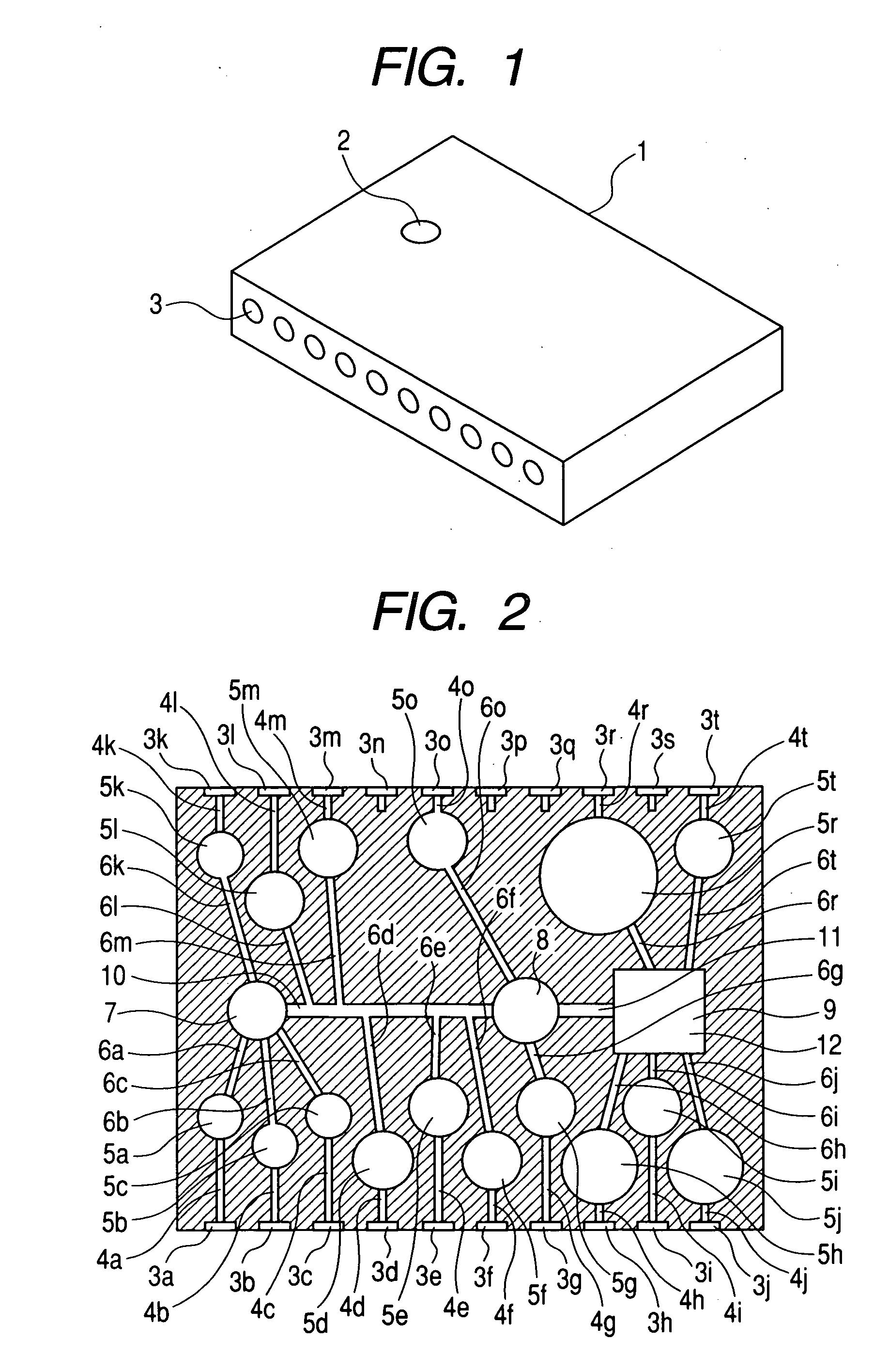
[0066]FIG. 1 is a perspective view of a biochemical reaction cartridge 1 contained in a biochemical treatment equipment system.

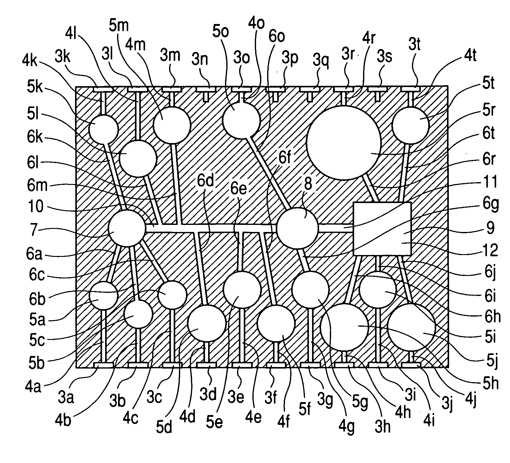
[0067] A sample inlet 2 for injecting a sample such as blood by use of a syringe or the like is provided on the upper portion of the biochemical reaction cartridge 1 and sealed with a rubber cap. Several nozzle inlets 3 that apply or reduce pressure by inserting nozzles therein for moving an internal solution are provided on the side of the cartridge 1. A rubber cap is fixed in each of the nozzle inlets 3. The other side of the cartridge 1 has the same structure.

[0068] These rubber caps are provided for preventing the entry of the air into the biochemical reaction cartridge 1.

[0069] The body of the biochemical reaction cartridge 1 is composed of a transparent or semitransparent synthetic resin such as polymethyl methacrylate (PMMA), an acrylonitrile-butadiene...

example 2

[0126] Example 2 of the present invention will be described in detail with reference to drawings.

[0127]FIG. 10 is a diagram showing an unused biochemical reaction cartridge 1 from the underside thereof, in which a shutter that covers an opening has no history indicating that the shutter is opened, once covering the opening. FIG. 11 is a sectional view taken along the A-A line in FIG. 10, in which a shutter 37 can be slid in the direction of the arrow a in FIG. 10. FIG. 12 shows a state in which the shutter 37 is moved in the direction of the arrow a and a stopper 42 is protruded in the direction of the arrow c.

[0128] In the present Example, the shutter 37 is used instead of the seal 30 to cover the opening. The shutter 37 that covers the opening is constructed in a stopper 38, an availability / unavailability display window 39, a torsion coil spring 40, a shutter cover 41 and the stopper 42.

[0129] The backside of a DNA microarray 12 is exposed by sliding the shutter 37 in the direc...

example 3

[0144] Example 3 of the present invention will be described in detail with reference to drawings.

[0145]FIG. 15 is a perspective view of the whole biochemical reaction cartridge 1. FIG. 16 is a diagram showing the backside of the biochemical reaction cartridge from the arrow D in FIG. 15. A shutter 37 has a C-shape capable of being slid in the directions of the arrows a and b in FIG. 16. In such a structure, a sample inlet2 and an opening on the backside of a DNA microarray 12 are constructed so that one of them is opened with the other closed.

[0146] Although detailed description is omitted, the DNA microarray is placed in the biochemical reaction cartridge with the shutter 37 opened, followed by the closing of the shutter 37, as in Example 2.

[0147]FIGS. 15 and 16 illustrate a state in which the sample inlet 2 is opened and the opening on the backside of the DNA microarray 12 is closed, that is, the unused state of the biochemical reaction cartridge.

[0148] In the present Example,...


PUM

PropertyMeasurementUnit
heightaaaaaaaaaa
widthaaaaaaaaaa
temperatureaaaaaaaaaa

Abstract

There is provided a biochemical reaction cartridge comprising at least one chemical reaction chamber that accommodates a solution for biochemically treating a sample, a reaction chamber for performing detection reaction of a target substance in the biochemically treated sample, and a detection reaction information fetching section for fetching information on whether or not the detection reaction is performed, wherein the biochemical reaction cartridge is provided with a covering unit that can cover and expose at least the reaction information fetching section.

Description

BACKGROUND OF THE INVENTION [0001] 1. Field of the Invention [0002] The present invention relates to equipment that analyzes cells, microorganisms, chromosomes, nucleic acids or the like in samples by use of biochemical reaction such as antigen-antibody reaction or nucleic acid hybridization, and to a biochemical treatment equipment system comprising a biochemical reaction cartridge used integrally with the equipment. [0003] 2. Related Background Art [0004] A vast majority of analyzers for analyzing samples such as blood use an immunological method that utilizes antigen-antibody reaction or a method that utilizes nucleic acid hybridization. For example, the analyzers use a protein such as an antibody or an antigen specifically binding to a substance to be detected or a single-stranded nucleic acid as a probe, which is in turn immobilized on the surface of a solid phase such as fine particles, beads or glass plates and subjected to antigen-antibody reaction or nucleic acid hybridizat...

Claims


Application Information

Patent Timeline
Patent Type & Authority Applications(United States)
IPC IPC(8): G01N31/22
CPCB01L3/502715B01L7/52B01L2200/10B01L2300/0636Y10T436/143333B01L2300/1822B01L2400/0487B01L2400/0622G01N31/22B01L2300/0816
Inventor YOKOYAMA, DAISUKE
Owner CANON KK
Why Eureka
Try Eureka