Wearable system for positive airway pressure therapy

a technology of positive airway pressure and wearable system, which is applied in the direction of positive displacement liquid engine, flexible member pump, machine/engine, etc., can solve the problems of limiting the patient's ability to move about, adversely affecting the daily activities of individuals, and serious sleep deprivation

Inactive Publication Date: 2006-05-11
AIR PROD & CHEM INC
View PDF49 Cites 168 Cited by
  • Summary
  • Abstract
  • Description
  • Claims
  • Application Information

AI Technical Summary

Benefits of technology

The technical effect of this patent is that it describes an air pump system which takes in regular air from the atmosphere and pushes it out through a mask to create high-pressure air for patients who require it. This helps keep their airways open while they breathe in or out.

Problems solved by technology

The technical problem addressed in this patent text is the need for improved positive airway pressure therapy devices that provide better sleeping comfort and increased compliance in the use of the devices by sleep apnea patients. The current devices are bulky and may limit a patient's ability to move about during sleep, which can cause discomfort and reduce compliance. The invention described below aims to address this problem by providing new positive airway pressure therapy devices that are more comfortable and easier to use.

Method used


Image

  • Wearable system for positive airway pressure therapy
  • Wearable system for positive airway pressure therapy
  • Wearable system for positive airway pressure therapy

Examples


example

[0096] The following Example illustrates embodiments of the present invention and does not limit these embodiments to any of the specific details described therein.

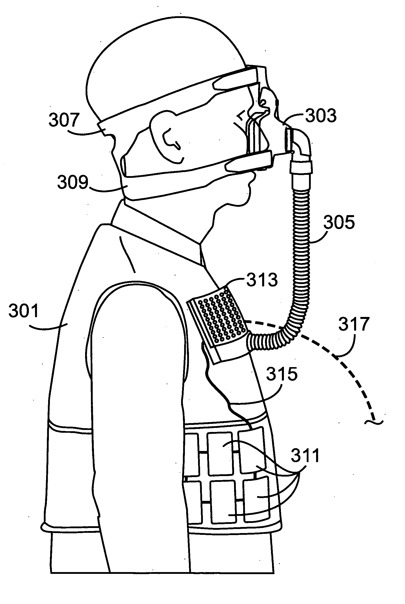
[0097] A pressurized air supply system utilizing the embodiment of FIG. 3 is designed to provide up to 100 lpm of air at pressures between 2 and 20 cm water and to operate in the CPAP mode. The system supplies the pressurized air to a sleep apnea patient for 8 hours while the patient sleeps. Based on the performance specifications from the paper of C. Cabuz et al cited above, each individual pump element of air pump system 313 can deliver pressurized air at 30 ml / min, requires 8 mW of power, and has overall dimensions of 1.5 cm×1.5 cm×0.1 cm. Each pump element generates air at a pressure up to 20 cm water, and 3,333 pump elements are operated in parallel to provide the required pressurized air flow rate of 100 lpm. The overall volume of air supply system 313 is 750 ml and the system is configured in a flat array 1 cm thi...


PUM


Abstract

Apparatus for providing positive airway pressure therapy comprising a mask adapted for the delivery of pressurized air to maintain positive airway pressure in a patient's airway and an air pump system comprising a plurality of pump elements adapted to supply pressurized air to the mask, wherein the air pump system is attached directly to the mask or is adapted to be worn on a part of the patient's body spaced apart from the mask.

Description


Claims


Application Information

Patent Timeline
Owner AIR PROD & CHEM INC
Why Eureka
Try Eureka