Substance testing devices with photo identification

a substance testing and photo identification technology, applied in the field of ignition interlock devices, can solve the problems of ineffective deterring dui offenses, presenting numerous difficulties and drawbacks, and high difficulty in comparing “breath patterns” accuracy, so as to facilitate photographic identification

Inactive Publication Date: 2006-05-11
BIOMETRIC EQUIP & SAFETY TECH LABS
View PDF3 Cites 2 Cited by
  • Summary
  • Abstract
  • Description
  • Claims
  • Application Information

AI Technical Summary

Benefits of technology

[0010] In another aspect, the present invention provides a method of identifying one or more individuals impaired by a controlled substance, the method comprising the steps of: providing a photographic unit; ascertaining the degree to which an individual is affected by a controlled substance; and operating the photographic unit, responsive to the ascertaining step, to facilitate photographic identification of an individual who is affected by a controlled substance beyond a predetermined threshold level.

Problems solved by technology

It has been found that a major drawback of conventional interlock devices is that they might not be effective in deterring DUI offenses if an individual other than the defendant (i.e., the person who has been assigned the interlock device) actually operates the interlock.
However, this solution has been found to present numerous difficulties and drawbacks.
For instance, accuracy in comparing “breath patterns” can be highly elusive.
Aside from cost considerations, a major drawback to such a device is that for purposes of motor vehicle operation, state statutes specify the manner in which blood-alcohol content is to be determined and spectroscopic analysis is generally not so specified.
It would not be sufficient to use fingerprint authentication for interlock devices, because as discussed above, the defendant may provide the authentication while someone else supplies a “clean” breath.

Method used


Image

  • Substance testing devices with photo identification
  • Substance testing devices with photo identification

Examples


Embodiment Construction

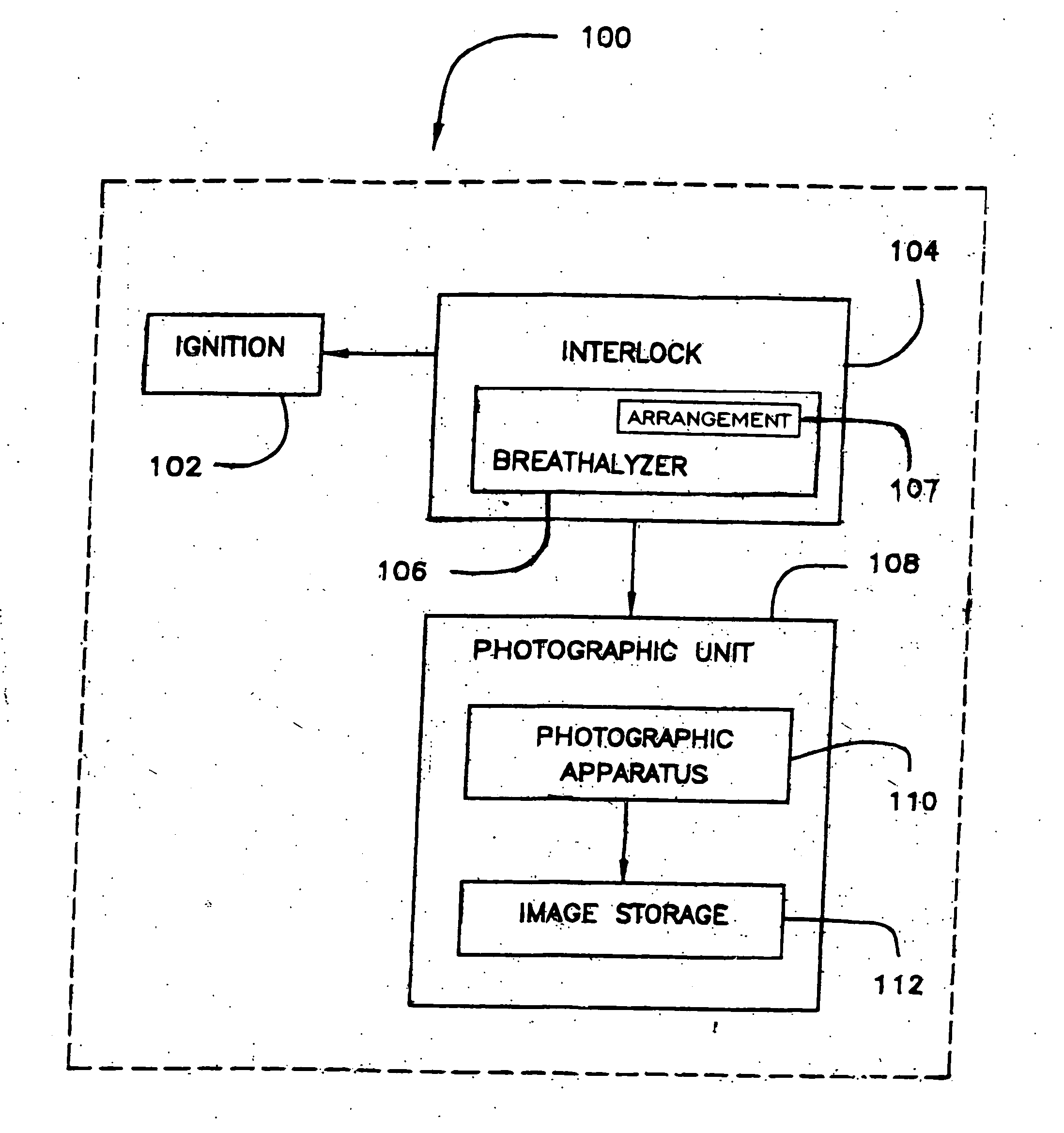
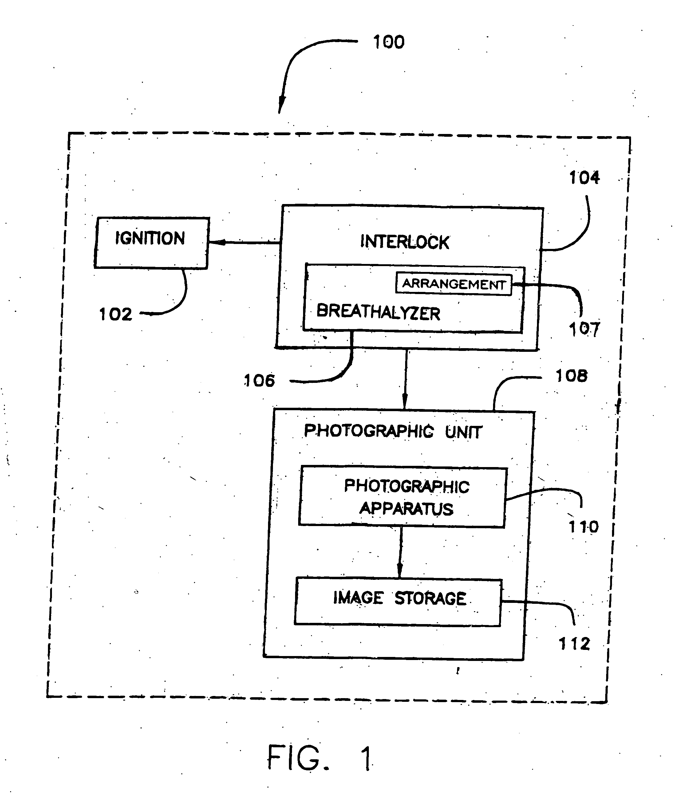
[0013]FIG. 1 schematically illustrates a motor vehicle 100 or other machinery in which an ignition interlock device, in accordance with at least one embodiment of the present invention, may be employed.

[0014] An ignition 102 of the vehicle 100 (or other machinery) may be engageable via interlock device 104. Interlock device 104 preferably includes a breathalyzer 106. A photographic unit 108, on the other hand, preferably includes a photographic apparatus 110 and image storage arrangement 112.

[0015] Preferably, an individual (who is likely a defendant required to use an ignition interlock device), when wishing to start the ignition 102, will take a test with breathalyzer 106 in conventional manner (e.g. via emitting a sufficient blow of his / her breath into the equipment). If the test determines a state of “under the influence” then, per usual, the interlock device 104 will engage to prevent activation of ignition 102 and, thus, operation of the vehicle 100 or other machinery. Prefe...


PUM


Abstract

A system which, in at least one embodiment, obtains a photographic image of an individual attempting to disengage an ignition interlock device or the like to assist in determining whether the individual is the same as one for whom the device is intended.

Description

CROSS REFERENCE TO RELATED APPLICATIONS [0001] This application is a continuation of prior U.S. patent application Ser. No. 10 / 026,728, filed Dec. 21, 2001, which is hereby incorporated by reference in its entirety as if fully set forth herein.FIELD OF THE INVENTION [0002] The present invention relates generally to ignition interlock devices, such as are used in vehicles of drivers with DUI convictions (who, e.g., are endowed with special driving privileges and are in that connection under supervision by a probation officer or the state as a condition of such privileges). BACKGROUND OF THE INVENTION [0003] Essentially, an ignition interlock is a device that includes a breathalyzer which prohibits a vehicle from starting if the breathalyzer returns a reading of “under the influence” (i.e., corresponding to a statutory level of impairment or even a lower level of impairment prescribed by the manufacturer). Several courts throughout the U.S. are now requiring that interlock devices be ...

Claims


Application Information

Patent Timeline
Patent Type & Authority Applications(United States)
IPC IPC(8): G08B23/00A61B5/00G08B13/196G08B15/00
CPCA61B5/18B60K28/063B60W2540/24G08B13/196G08B13/19647G08B13/19695G08B23/00
Inventor CRESPO, PIERRE M.
Owner BIOMETRIC EQUIP & SAFETY TECH LABS
Why Eureka
Try Eureka