Vent baffle and perforation machine

a technology of perforation machine and vent baffle, which is applied in ventilation systems, lighting and heating apparatus, heating types, etc., can solve the problems of roof damage, ice formation on the roof, and negatively affecting the performance of attic insulation

a technology of perforation machine and vent baffle, which is applied in ventilation systems, lighting and heating apparatus, heating types, etc., can solve the problems of roof damage, ice formation on the roof, and negatively affecting the performance of attic insulation

US20060105699A1Inactive Publication Date: 2006-05-18BRENTWOOD INDS

Image

  • Vent baffle and perforation machine
  • Vent baffle and perforation machine
  • Vent baffle and perforation machine

Examples


Embodiment Construction

[0030] Certain terminology is used in the following description for convenience only and is not limiting. The words “right”, “left”, “top”, and “bottom” designate directions in the drawings to which reference is made. The words “interior” and “exterior” refer to directions towards and away from, respectively, the geometric center of the vent baffle or designated parts thereof. Furthermore, as used herein, the word “a” or a singular component includes the plural or more than one component, unless specifically and explicitly restricted to the singular or a single component or unless a singular meaning is apparent from the context. The terminology includes the words above specifically mentioned, derivatives thereof and words of similar meaning.

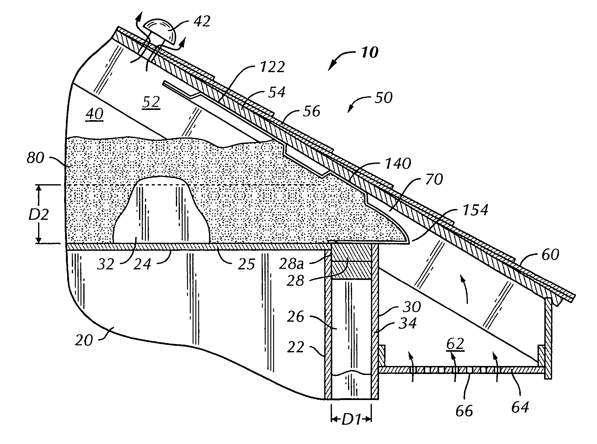
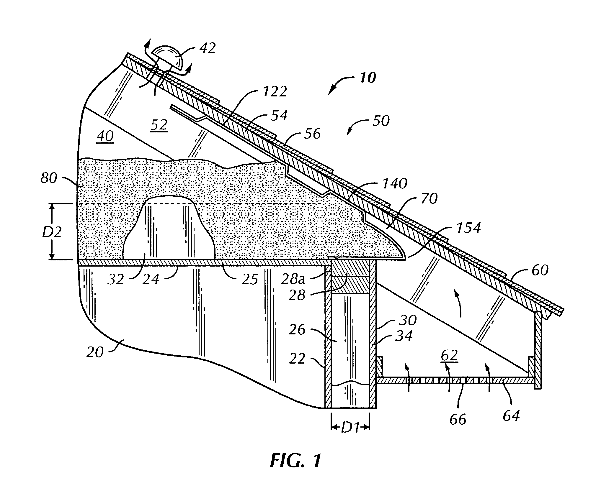
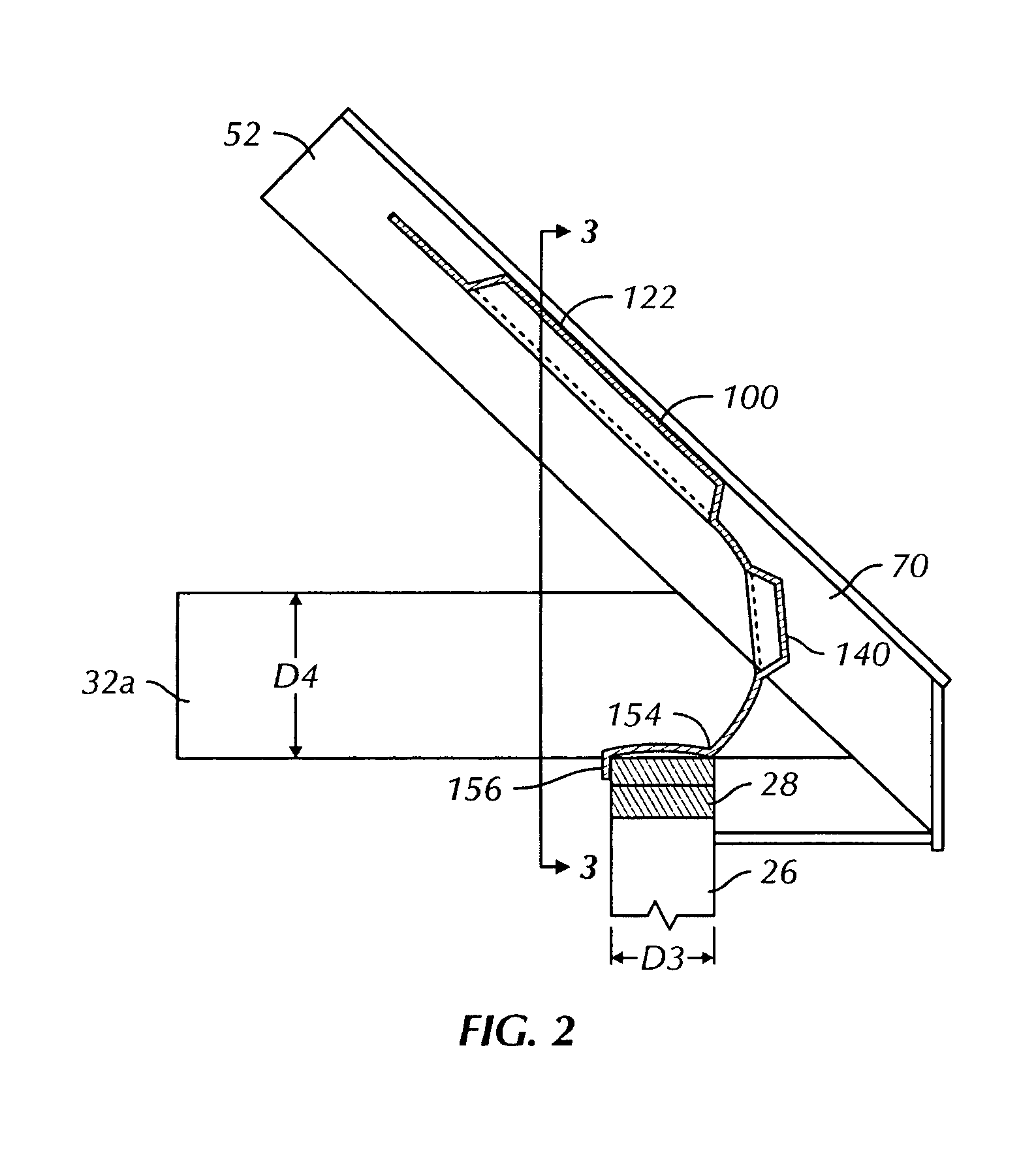
[0031] Referring to the drawings, wherein like reference numerals are used to designate the same components throughout the figures, there is shown in FIGS. 1-7 two preferred, non-limiting embodiments of a vent baffle 100. The vent baffle 100 is ...


PUM

PropertyMeasurementUnit
distanceaaaaaaaaaa
distanceaaaaaaaaaa
sizeaaaaaaaaaa

Abstract

An adaptable vent baffle mountable to an underside of a roof deck and to a wall plate of a building structure between a pair of roof rafters having a rafter spacing for permitting ventilation between a soffit and an attic space of the building structure. A main body portion has a longitudinal axis and is positioned generally on a main body plane. A spacer extends from the main body portion and a tail portion is hingedly mounted to the main body portion. The main body portion and tail portion include first and second side edges and a baffle width is defined between the first and second side edges. At least one line of weakness extends generally parallel to the longitudinal axis for modifying the baffle width to adapt to the rafter spacing. A perforating machine for forming perforated lines on the vent baffle is also disclosed.

Description

CROSS-REFERENCE TO RELATED APPLICATIONS [0001] This application is a continuation-in-part application of U.S. patent application Ser. No. 10 / 811,632, filed Mar. 29, 2004 and titled, “Vent Baffle and Method of Installation”, the disclosure of which is incorporated herein by reference.BACKGROUND OF THE INVENTION [0002] The invention is in the field of building construction materials and particularly relates to attic vent baffles commonly used in residential building structures to allow ventilation flow through soffit vents into an attic space. [0003] It is known to provide attic ventilation systems to properly ventilate the attic space often found in buildings. Ventilation of the attic space is desirable to help prevent formation of condensation along the interior surface of the roof, which can damage attic insulation and the building structure itself. Proper ventilation also helps to prevent premature melting of snow accumulated on a building roof. Such premature melting can lead to ...

Claims


Application Information

Patent Timeline
18 May 2006
Publication
US20060105699A1
IPC
F24F7/02; E04D13/152; E04D13/17
CPC
B26D1/08; B26D9/00; B26F1/20; E04D13/152; E04D13/178; F24F7/02; Y10T83/0215; Y10T83/0385
Inventors
KORTUEM, MATT; RYE, PALLE