Storage bin assembly

a technology for storage bins and assemblies, which is applied in the field of storage bin assemblies for vehicles, can solve the problems of restricting the design tolerances of fore-aft overhead assemblies

Inactive Publication Date: 2006-06-22
INTIER AUTOMOTIVE INC
View PDF25 Cites 45 Cited by
  • Summary
  • Abstract
  • Description
  • Claims
  • Application Information

AI Technical Summary

Problems solved by technology

Such stowage bin doors have been typically designed to pivot about a single axis, which typically restricts fore-aft design tolerances of the overhead assembly.

Method used


Image

  • Storage bin assembly
  • Storage bin assembly
  • Storage bin assembly

Examples


Embodiment Construction

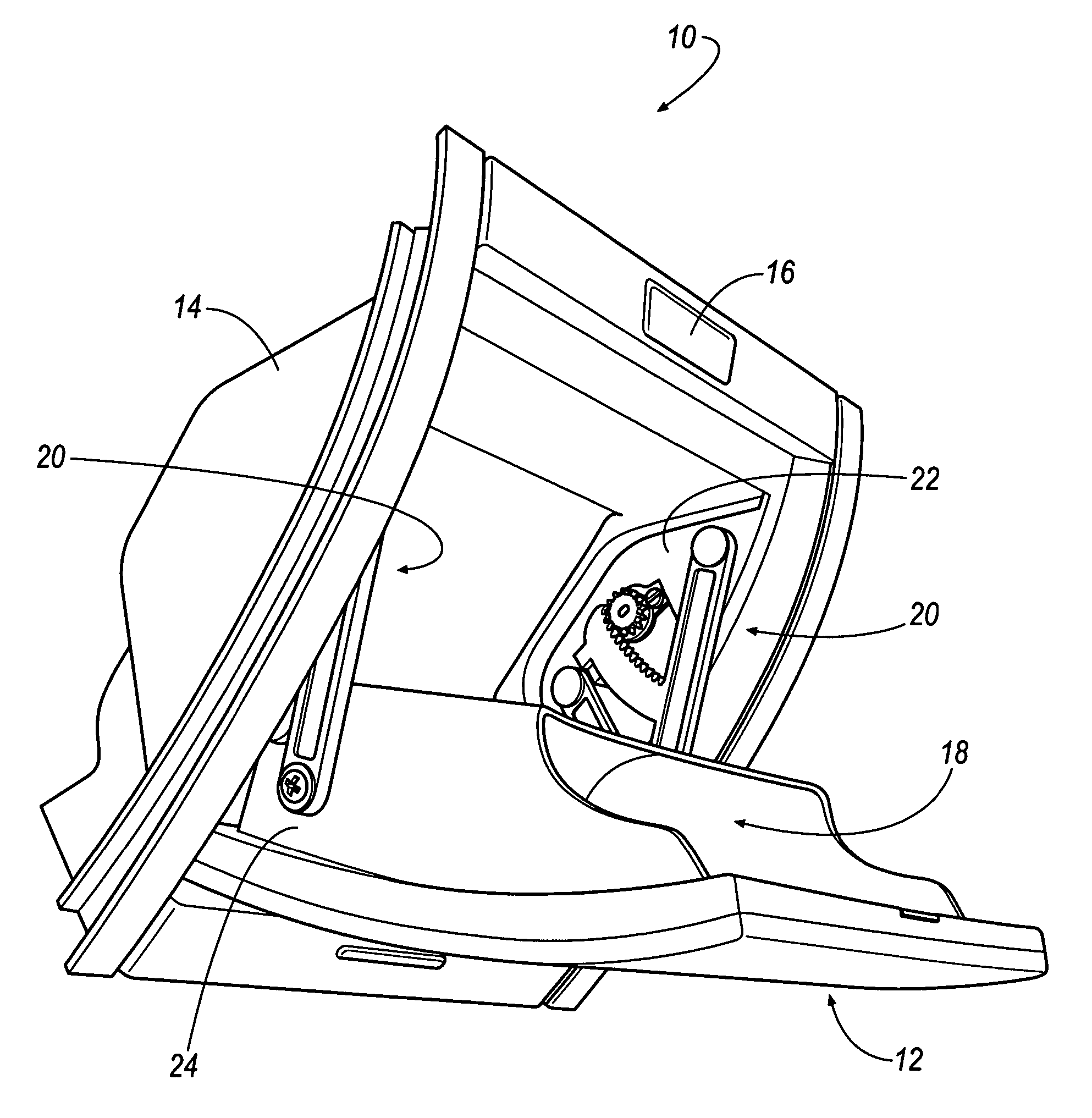
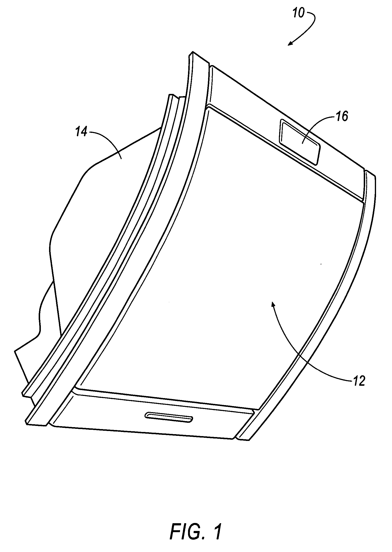
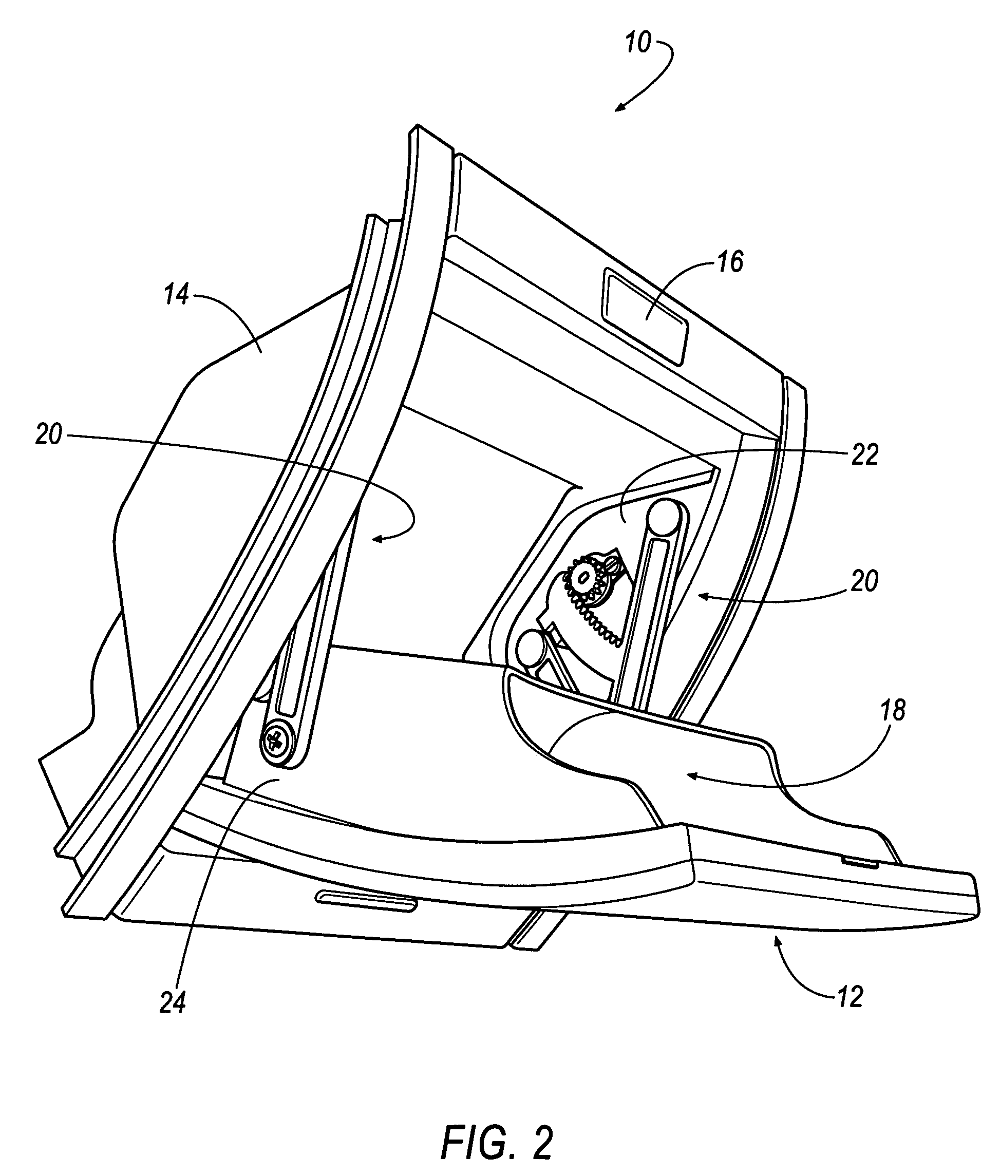
[0011] The above described disadvantages are overcome and a number of advantages are realized by an inventive storage bin assembly, which is seen generally at 10 in FIGS. 1 and 2. In general, the storage bin assembly 10 comprises a door 12 and an enclosure 14. If desired, a button 16 may be located on the storage bin assembly 10 at any desirable location to cause an un-latching or to initiate movement of the door 12 relative the enclosure 14. However, it will be appreciated that the design of the storage bin assembly 10 may not include the button 16 and that the door 12 may be initially moved relative the enclosure 14 with a conventional ‘push-push’ mechanism, or the like. Referring to FIG. 2, the door 12 is illustrated in a fully deployed position and includes an integral storage compartment 18 for stowing sunglasses, maps, and the like. The storage compartment 18 substantially occupies the entire volume of the enclosure 14 when the door 12 is in the stowed position.

[0012] In gene...


PUM


Abstract

A storage bin assembly is disclosed. The storage bin assembly includes a door moveably connected to an enclosure at first and second pivot axes by a pair of compound pivoting mechanisms including a first arm and a second arm. The storage bin assembly also includes an arcuate dampening arm integrally connected to the first arm of each pivoting mechanism to provide damped movement of the door relative the enclosure. A method for adjusting the position of the door relative the enclosure is also disclosed.

Description

CLAIM TO PRIORITY [0001] This application claims the benefit of U.S. Provisional Application No. 60 / 638,673, filed Dec. 22, 2004, the contents of which are incorporated by reference.TECHNICAL FIELD [0002] The present disclosure generally relates to vehicular overhead storage bin assemblies. More particularly, the disclosure relates to an overhead storage bin assembly including a compound pivoting mechanism for causing movement of a storage bin door relative an enclosure. BACKGROUND OF THE INVENTION [0003] It is known in the art that vehicular overhead assemblies have typically included a variety of components, such as, for example, storage bins, for stowing any desirable item, such as, for example, sunglasses, maps, and the like. Such stowage bin doors have been typically designed to pivot about a single axis, which typically restricts fore-aft design tolerances of the overhead assembly. As a result, design considerations of overhead assemblies become constrained by the location of ...

Claims


Application Information

Patent Timeline
Patent Type & Authority Applications(United States)
IPC IPC(8): A47B96/04
CPCB60R7/04B64D11/003
Inventor BECKLEY, DANIEL V.
Owner INTIER AUTOMOTIVE INC
Why Eureka
Try Eureka