Upright manual shears

Inactive Publication Date: 2006-06-29
MIDWEST TOOL & CUTLERY
View PDF9 Cites 16 Cited by
  • Summary
  • Abstract
  • Description
  • Claims
  • Application Information

AI Technical Summary

Problems solved by technology

Often this work requires reaching into places of limited accessibility where a user must make cuts while reaching overhead or down in an uncomforta

Method used


Image

  • Upright manual shears
  • Upright manual shears
  • Upright manual shears

Examples


Embodiment Construction

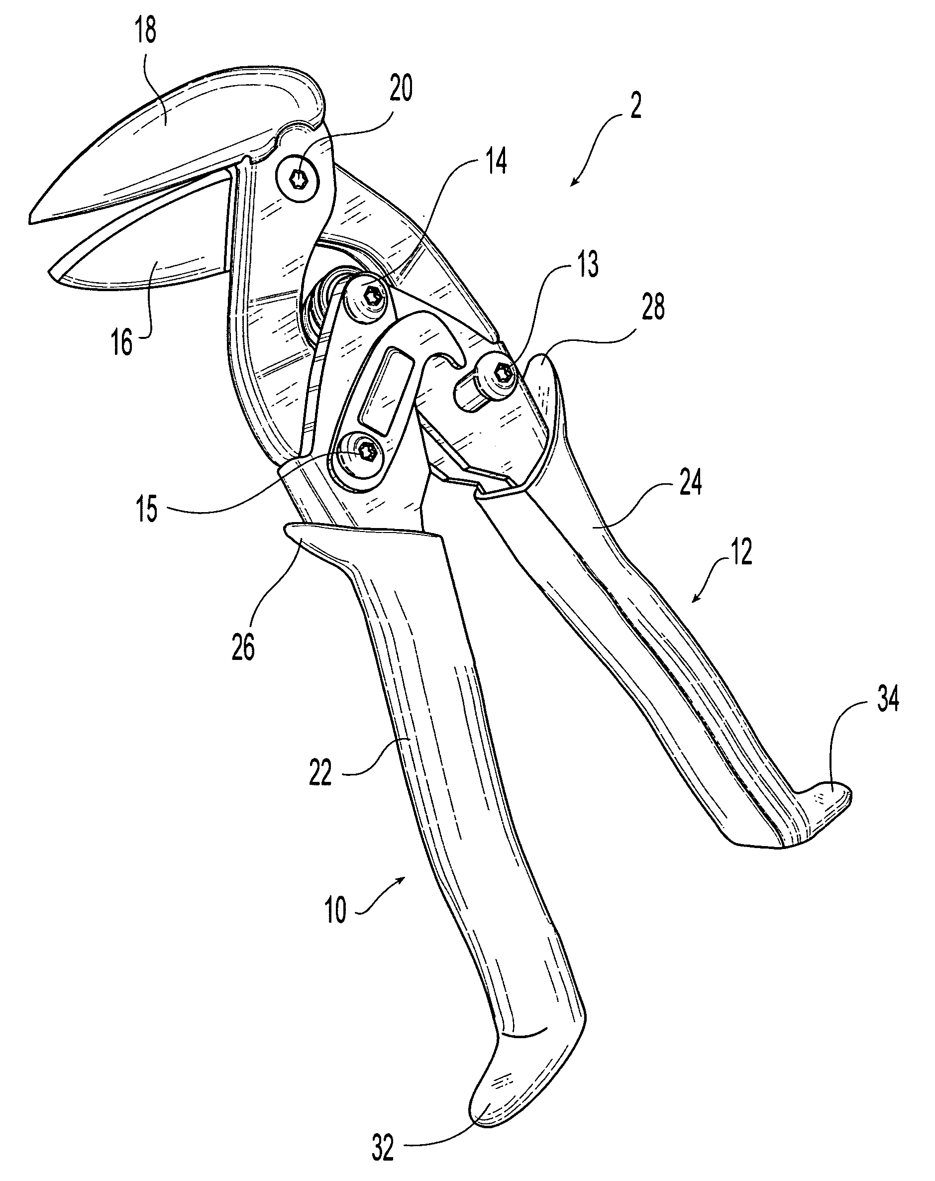
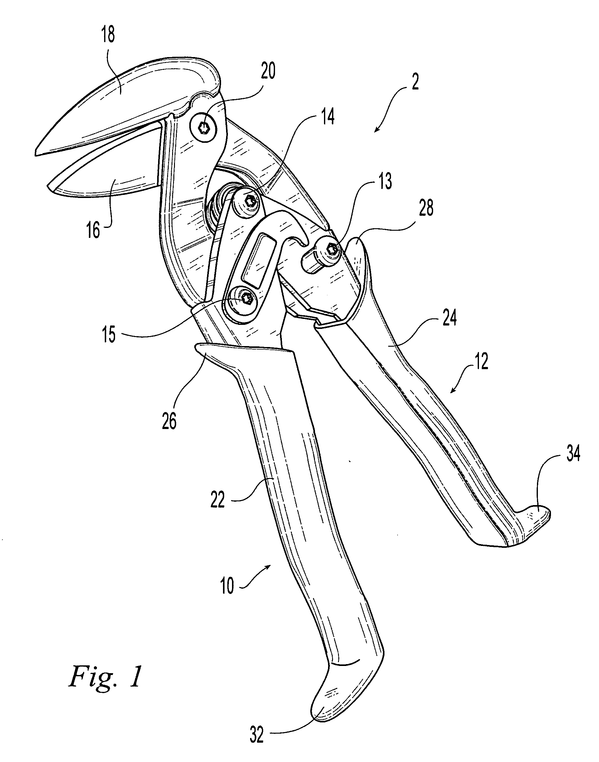
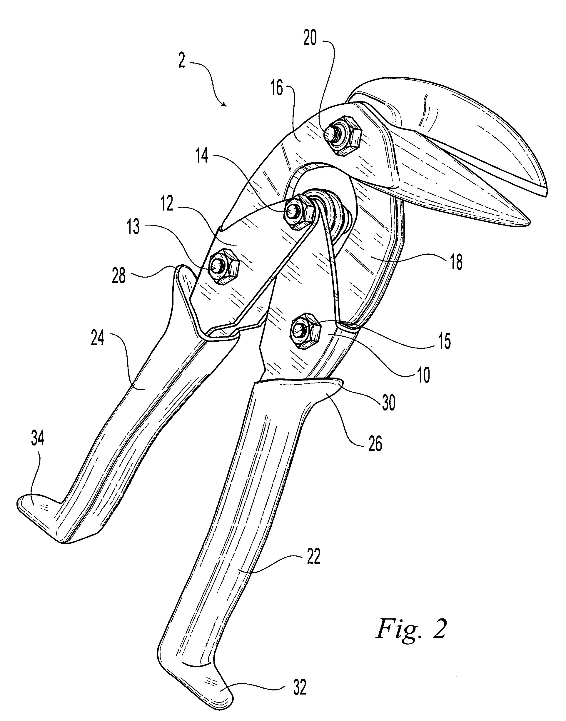
[0015]FIGS. 1-4 illustrate the preferred embodiment of the hand operated, cutting shears of the invention. The shears 2 of FIGS. 1-3 are straight and right cut shears while the shears of FIG. 4 are straight and left cut shears, the difference being the relative positioning of the top and bottom blades to the left or right of the user when they are gripped in the same orientation. However, the left and right cut variations do not affect the principles of the present invention. The shears have a pair of handles 10 and 12 pivotally connected as levers to a lower pivot 14. The handles 10 and 12 are also connected at pivots 13 and 15 in a compound linkage arrangement to a pair of intersecting cutting blades 16 and 18. The cutting blades are pivotally connected together at an upper pivot 20.

[0016] Hand grips 22 and 24 are formed on and envelope each of the handles 10 and 12 distally from the lower pivot 14. Each hand grip 22 and 24 includes an outwardly projecting upper hand grip tab, 26...


PUM

PropertyMeasurementUnit
Distanceaaaaaaaaaa

Abstract

Cutting shears having a pair of handles pivotally connected as levers to a lower pivot and pivotally connected in a compound linkage arrangement to a pair of intersecting cutting blades at an upper pivot. A hand grip on each of the handles includes an outwardly projecting upper hand grip tab and the distance from the upper pivot to a hand contacting surface of each upper hand grip tab is substantially in the range from 2½″ to 3¼″ and preferably substantially 2¾″. The distance from the locus of intersections of the blades as they pivot through a cutting motion to the plane of the most distal tips of the handles is substantially within range from 6¾″ to 7¼″ and preferably 7″. The hand grips are substantially identically, arcuately, outwardly, oppositely contoured and longitudinally symmetrical. Each hand grip also has an outwardly projecting lower hand grip tab and the hand contacting surfaces of the upper and lower tabs on each hand grip are spaced apart a distance substantially 4½″ although they may be substantially within the range of 4¼″ to 4¾″. The tabs protrude outwardly from an intermediate portion of the hand grips preferably by ½″.

Description

BACKGROUND OF THE INVENTION [0001] 1. Field of the Invention [0002] This invention relates generally to hand tools and more particularly to cutting tools known in the art as shears or snips which utilize a levered, scissors action for cutting sheet stock such as sheet metal. [0003] 2. Description of the Related Art [0004] An extensive variety of shears of this type have been developed over many decades. Such shears are hand operated and have a pair of handles attached to a pair of blade and having one or more pivotal connections as levers. In many such shears a spring urges the handles apart to an ungripped state so the user needs merely to relax the user's hand to allow the shears to open before making the next cut. They are commonly provided with a latch for storing them is a closed position. [0005] More recent shears have a pair of handles pivotally connected as levers to a lower pivot and pivotally connected in a compound linkage arrangement to a pair of intersecting cutting bla...

Claims


Application Information

Patent Timeline
IPC IPC(8): B26B13/00
CPCB23D29/026B26B13/26
Inventor DETER, STEPHEN D.
Owner MIDWEST TOOL & CUTLERY
Why Eureka
Try Eureka