Addressing schemes for electronic displays

a technology of electronic displays and address schemes, applied in the direction of electric digital data processing, instruments, computing, etc., can solve the problems of preventing their widespread use, inadequate service life of these displays, and normally precluding the use of passive matrix addressing methods

Inactive Publication Date: 2006-06-29
E INK CORPORATION
View PDF99 Cites 193 Cited by
  • Summary
  • Abstract
  • Description
  • Claims
  • Application Information

AI Technical Summary

Benefits of technology

[0017] This invention also provides an electronic display comprising an electro-optic material having a plurality of separatel

Problems solved by technology

Nevertheless, problems with the long-term image quality of these displays have prevented their widespread usage.
For example, particles that make up electrophoretic displays tend to settle, resulting in inadequate service-life for these displays.
This normally precludes the use of passive matrix addressing methods.
One problem with such high resolution displays is the sheer number of drivers required.
Especially in small displays, the

Method used


Image

  • Addressing schemes for electronic displays
  • Addressing schemes for electronic displays
  • Addressing schemes for electronic displays

Examples


Embodiment Construction

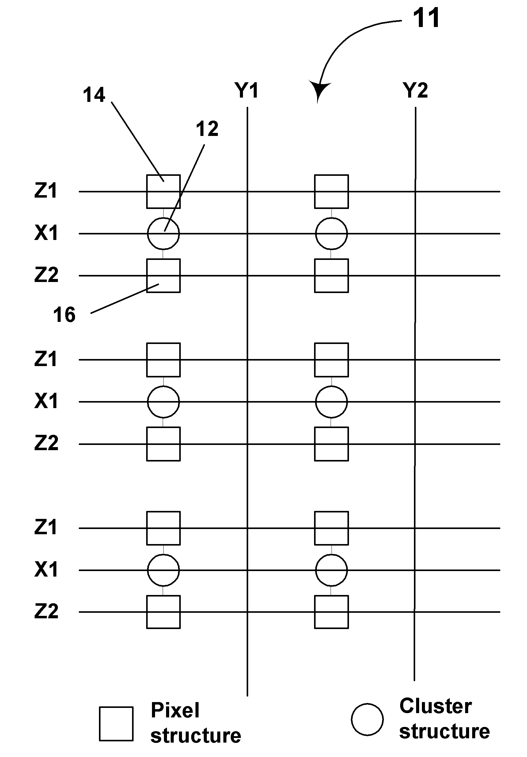
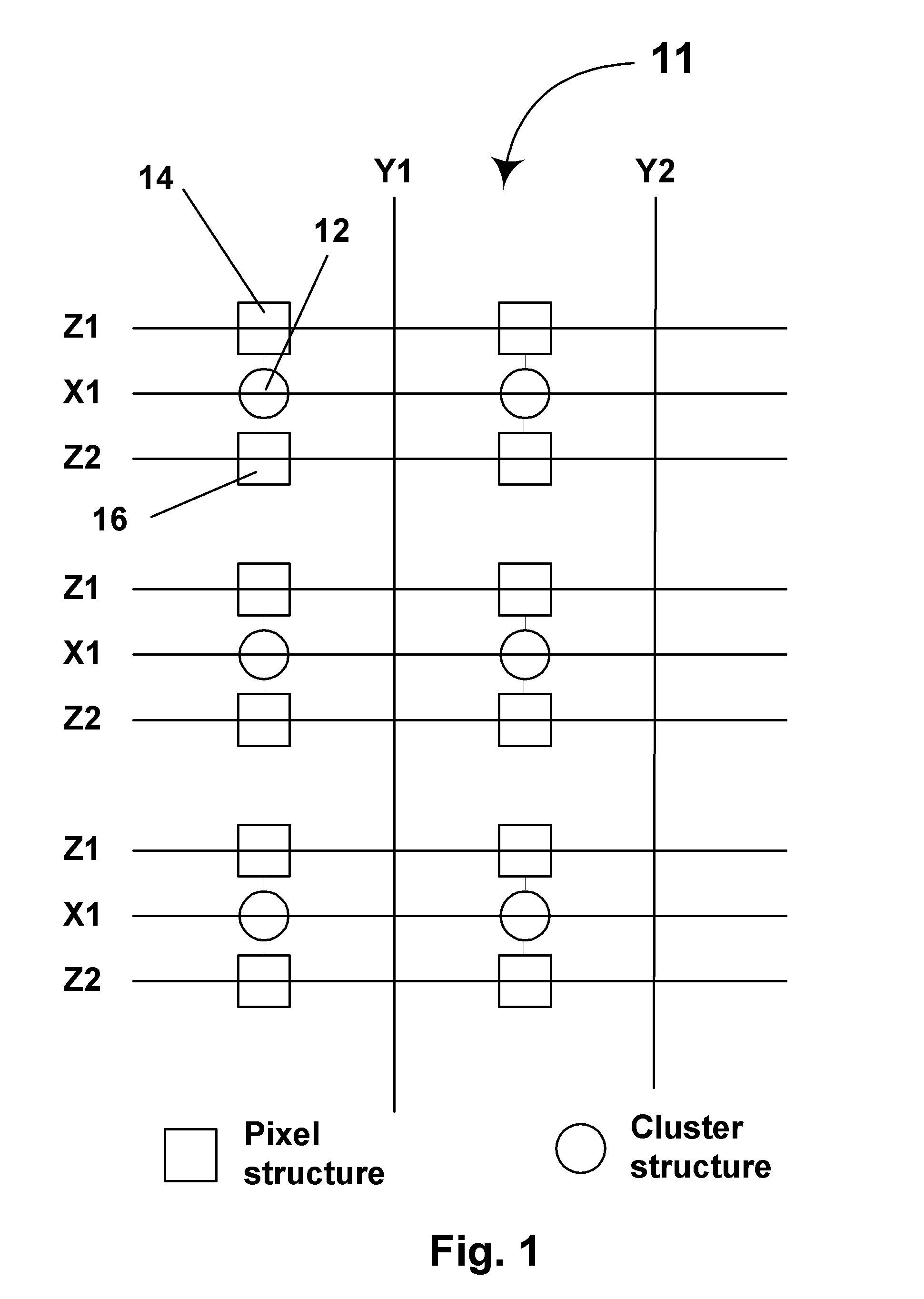
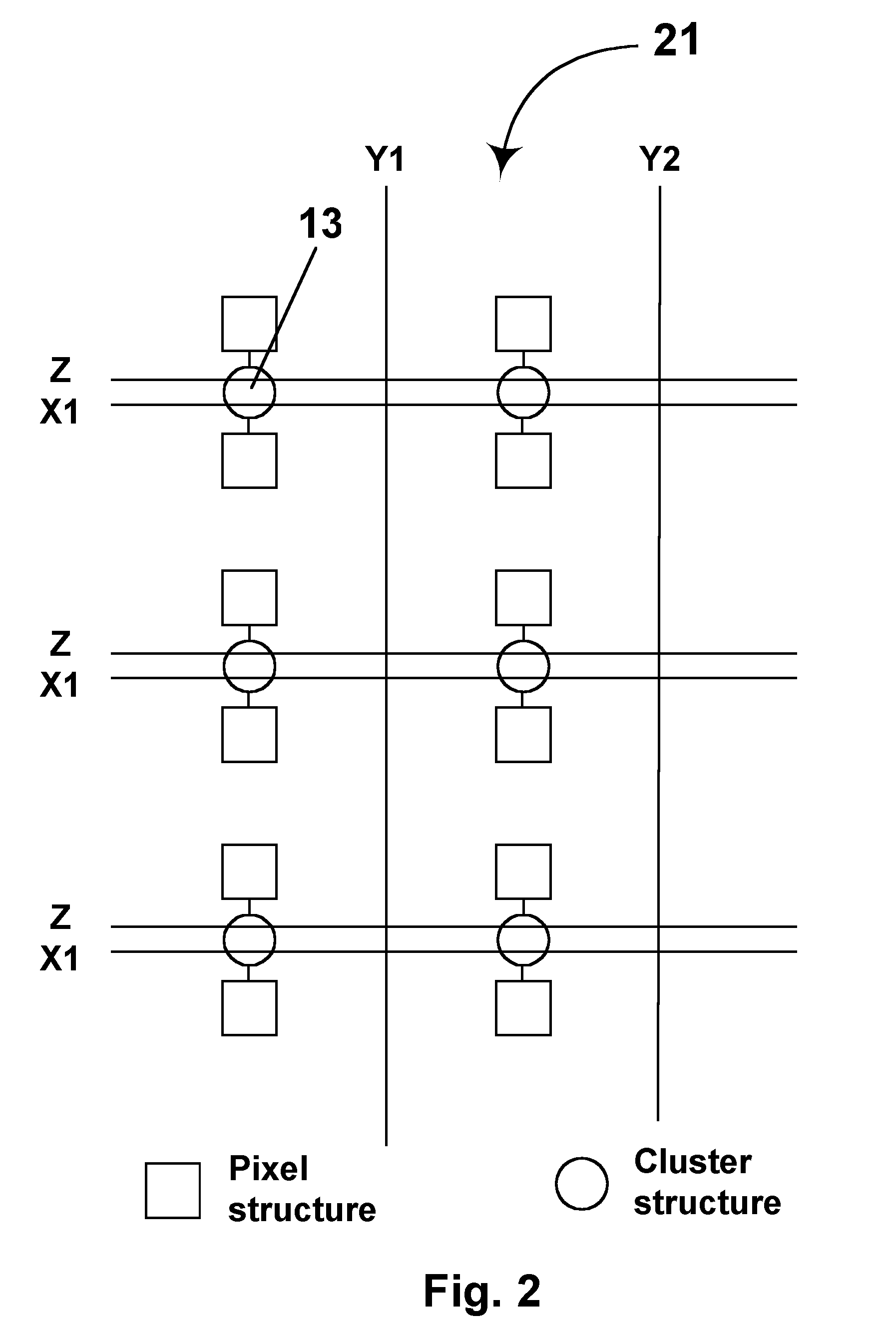
[0070] As already mentioned, the three dimensional displays and methods of the present invention use an electro-optic material having a plurality of pixels, and separate first, second and third sets of addressing means for addressing the pixels. In this display and method, each of the pixels is associated with one addressing means in each of the three sets, such that addressing of any specific pixel requires application of signals within predetermined ranges to each of the three addressing means associated with that specific pixel. The additional dimension is accomplished by introducing a method of addressing sub-arrays within the array. By thus substituting a three-dimensional addressing scheme for a two-dimensional one, the number of drivers can be greatly reduced. In effect, the present invention splits the display into z regions, each addressable by the x columns and y rows, enabling the entire display of x*y*z pixels to be addressed by x+y+z drivers. For example, the aforementi...


PUM

PropertyMeasurementUnit
Coloraaaaaaaaaa
Sizeaaaaaaaaaa
Electric chargeaaaaaaaaaa

Abstract

An electronic display comprises an electro-optic material (preferably an electrophoretic medium) having a plurality of pixels, and separate first, second and third sets of addressing means for addressing these pixels. Each of the pixels is associated with one addressing means in each of the three sets, such that addressing of any specific pixel requires application of signals within predetermined ranges to each of the three addressing means associated with the specific pixel being addressed. The display may be in the form of a multi-page electronic book.

Description

REFERENCE TO RELATED APPLICATIONS [0001] This application is a continuation-in-part of copending application Ser. No. 09 / 683,179, filed Nov. 29, 2001 (Publication No. 2003 / 0063661), which itself claims benefit of Provisional Application Ser. No. 60 / 253,892 filed Nov. 29, 2000. This application is also a continuation-in-part of copending application Ser. No. 08 / 983,404, filed Jul. 19, 1996, which is the U.S. national phase of International Application PCT / US96 / 12000 (Publication No. WO 97 / 04398), filed Jul. 19, 1996, which in turn is (as regards the United States of America) a continuation-in-part of application Ser. No. 08 / 504,896, filed Jul. 29, 1995 (now U.S. Pat. No. 6,124,851). [0002] The entire disclosures of all the aforementioned applications, and of all U.S. patents and published and copending applications mentioned below, are herein incorporated by reference.BACKGROUND OF INVENTION [0003] The present invention relates to addressing schemes for electronic displays, that is t...

Claims


Application Information

Patent Timeline
IPC IPC(8): G09G3/34
CPCG02F1/1334G02F1/167G02F2001/1676G02F2201/12G09G3/02G09G3/344G09G3/3446G09G2300/08G09G2310/02G09G2310/0213G09G2310/0221G09G2310/0297G09G2310/04G09G2310/061G09G2320/0252G09G2340/16G09G2360/16
Inventor JACOBSON, JOSEPH M.COMISKEY, BARRETTWILCOX, RUSSELL J.
Owner E INK CORPORATION
Why Eureka
Try Eureka