Eureka AIR delivers breakthrough ideas for toughest innovation challenges, trusted by R&D personnel around the world.

Dome structure and installation apparatus therefor

Inactive Publication Date: 2006-07-27
PAINCHAUD GERALD
View PDF0 Cites 9 Cited by
  • Summary
  • Abstract
  • Description
  • Claims
  • Application Information

AI Technical Summary

Benefits of technology

[0009] It is therefore an aim of the present invention to provide an improved dome structure that requires a minimum amount of force to be deployed and or collapsed.
[0010] It is another aim of the present invention to provide an improved dome structure that is foldable into a compact configuration.

Problems solved by technology

This dome, particularly intended to cover a pool, requires a substantial amount of force to be deployed and collapsed.
The incorporation of such components into the dome structure causes the price to increase greatly making the dome unaffordable for many.
Although the use of a manual jack eliminates the need for a motor and consequently the cost thereof, the fact remains that an excessive amount of effort by an individual is necessitated to manually raise and lower the dome.
Also, the dome of U.S. Pat. No. 5,004,001 is not practical to use for most other applications, such as to cover a spa, as it is designed to cover a large area, and it cannot be easily stored without taking up too much space as it is not foldable.
Furthermore, a problem which is typically encountered by dome manufacturers is the securement of the fabric to the arched members of the dome.
The procedure involved can be laborious even for an experienced worker.
For the original manufacturer of the dome, shipping the structure with the fabric already secured at the factory then becomes more expensive as it must be shipped with care to ensure that the fabric is not damaged.
In the occurrence that the fabric is torn, unattached or otherwise damaged, the replacement of the fabric becomes a problem since the distributors may not have the necessary tools, equipment or expertise to repair the dome.

Method used


Image

  • Dome structure and installation apparatus therefor
  • Dome structure and installation apparatus therefor
  • Dome structure and installation apparatus therefor

Examples


Embodiment Construction

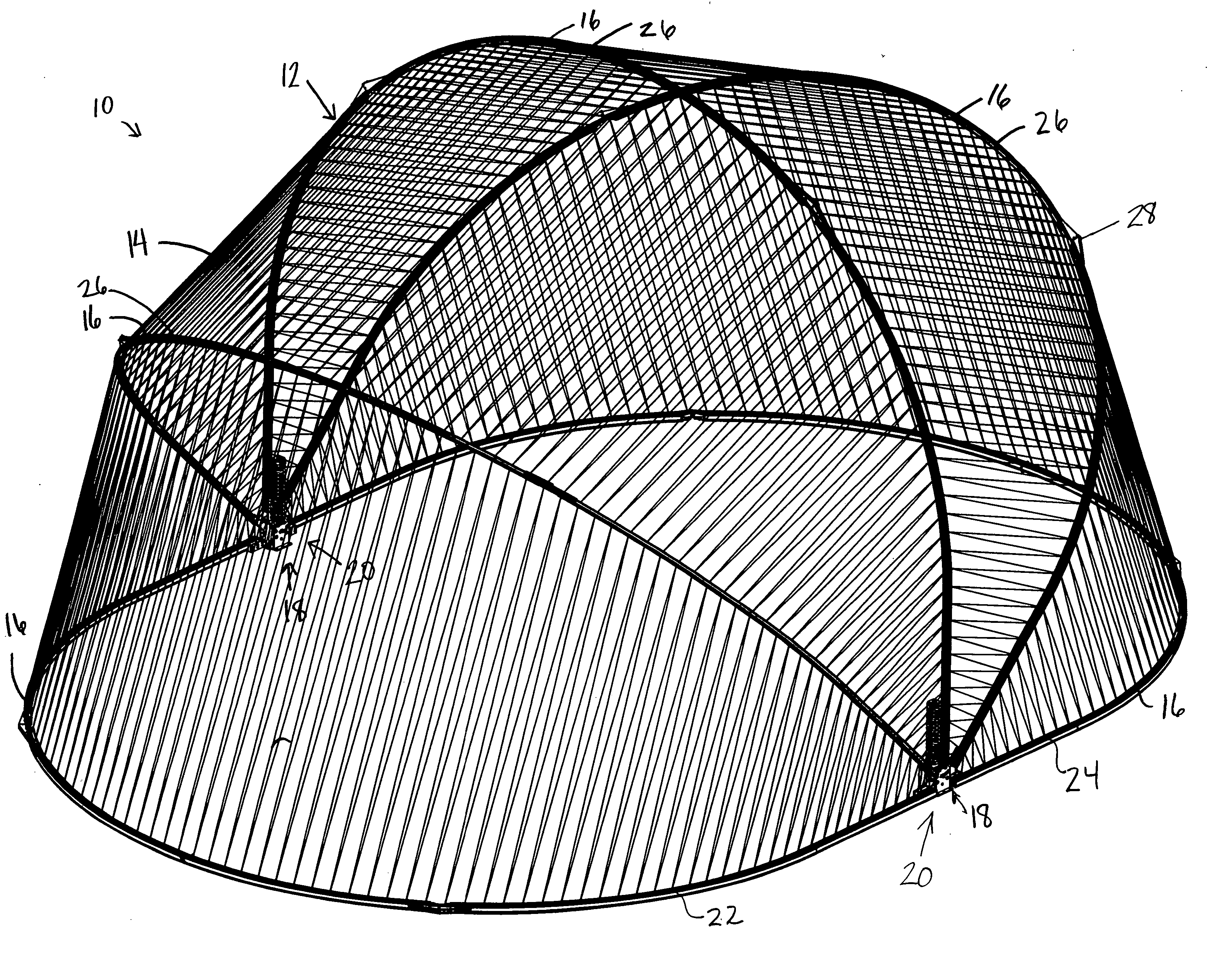
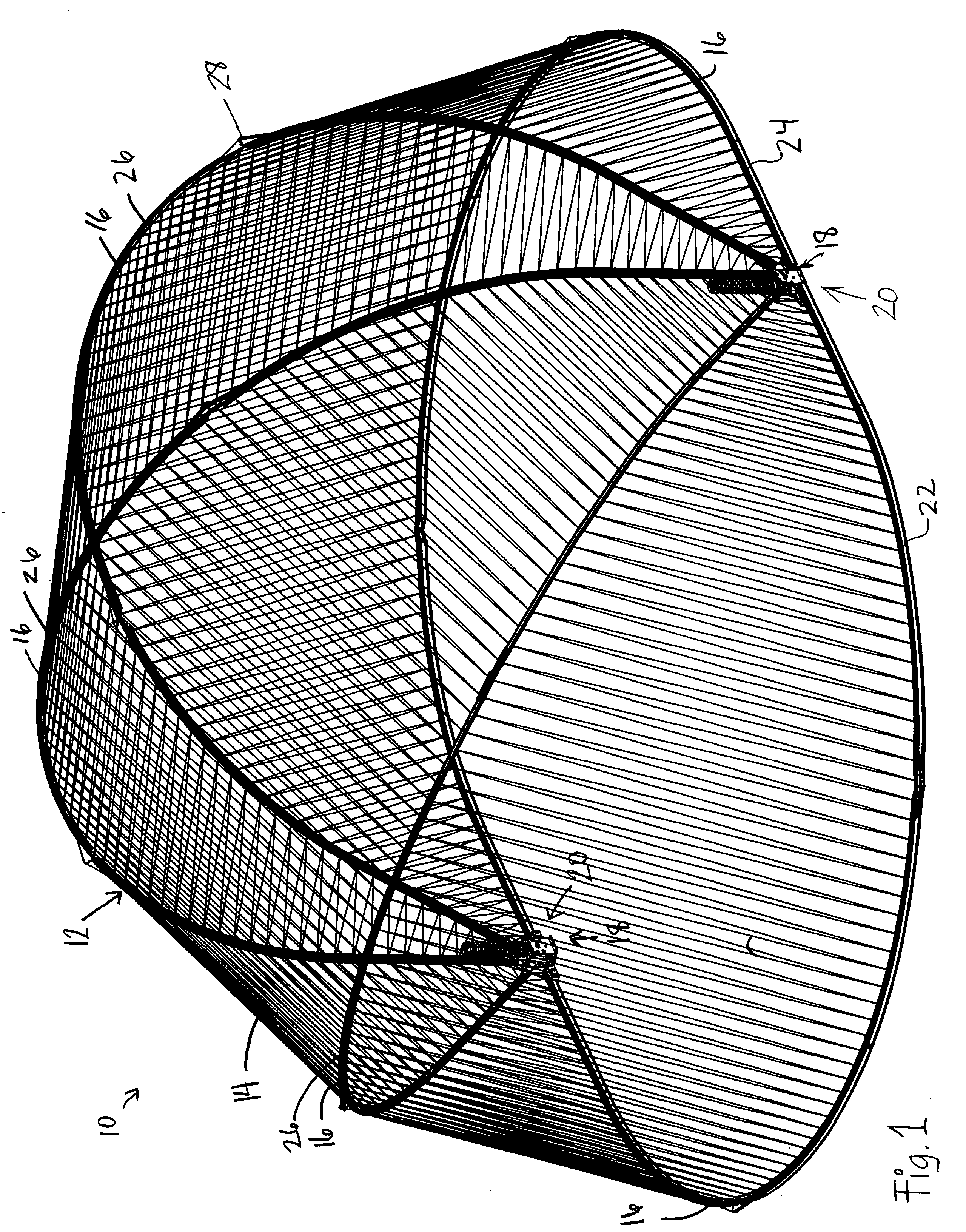
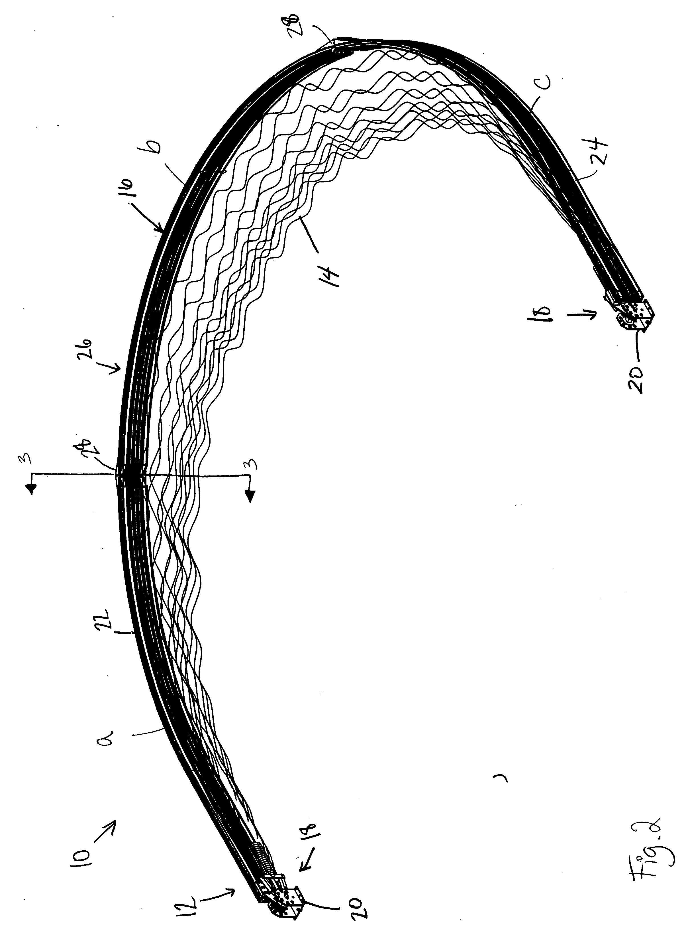
[0036] Referring to the drawings in greater detail and by reference characters thereto, there is illustrated in FIGS. 1 and 2 a preferred embodiment of a dome structure, identified by reference numeral 10, in a deployed position and in a collapsed position respectively. The dome structure 10 is made up of a supporting structure or frame 12 and a fabric 14 attached thereto. The structure 12 includes a plurality of arched members 16 pivotally connected at both ends 18 to a pair of spring loaded assemblies 20. More particularly, the plurality of arched members 16 can be further described as a first and a second arched member 22, 24, with intermediate arched members 26 therebetween. In this exemplary embodiment there are three intermediate arched members 26. Naturally, the number of intermediate arched members 26 may vary according to the design of the dome structure 10.

[0037] Referring to FIG. 1, when the dome structure 10 is deployed on the ground the first and second arched members ...


PUM


Abstract

A dome structure movable between a collapsed position and a deployed position. The dome structure comprising a plurality of arched members including first and second arched members and intermediate arched members therebetween. The dome structure also comprising a variable force generating device connected to the plurality of arched members for assisting in moving the dome structure between the collapsed position and the deployed position. The variable force generating device generating a variable force having a variation curve selected to substantially correspond to a curve of the force required for moving the dome structure between the collapsed position and the deployed position.

Description

BACKGROUND OF THE INVENTION [0001] 1. Field of the Invention [0002] The present invention relates to a dome structure and more particularly, relates to an improved dome structure that is foldable and requires a minimum amount of force to be deployed and collapsed, and an installation apparatus therefor. [0003] 2. Background Art [0004] The manufacture and use of various types of dome structures is known in the art. These range from fixed domes to collapsible domes that can be deployed when needed and folded into a compact configuration thereafter. An example of a collapsible dome is shown in U.S. Pat. No. 5,004,001, which teaches a foldable dome structure including means for raising and lowering the dome. This dome, particularly intended to cover a pool, requires a substantial amount of force to be deployed and collapsed. Such means as hydraulic, pneumatic or manual jacks are required to create the necessary force. The incorporation of such components into the dome structure causes t...

Claims


Application Information

Patent Timeline
IPC IPC(8): E04H15/36
CPCE04H15/38
Inventor PAINCHAUD, GERALD
Owner PAINCHAUD GERALD
Why Eureka
Eureka Blog
Learn More