Drive device and drive method of a light emitting display panel

a technology of light-emitting display panel and drive device, which is applied in the direction of instruments, static indicating devices, etc., can solve the problems of deteriorating lighting time rate, reducing the substantial light-emitting intensity of el elements, and delay in the start of light-emitting of el elements, etc., and achieves the effect of lowering the setting

Inactive Publication Date: 2006-08-03
TOHOKU PIONEER CORP
View PDF5 Cites 12 Cited by
  • Summary
  • Abstract
  • Description
  • Claims
  • Application Information

AI Technical Summary

Benefits of technology

[0038] The present invention has been developed, paying attention to the problem of shadowing generated particularly in a case where the lighting ratio of EL elements for each scan line is low as described above and the problem that the lower the setting of the dimmer value by dimmer control, the more prominent the shadowing occurs, and it is an object of the present invention to provide a drive device and a drive method of a light emitting display panel in which this shadowing can be reduced to a level at which this does not become a problem in practical use.

Problems solved by technology

Therefore, a problem arises in that a start of light emission of the EL element delays (slows down).
This deteriorates the lighting time rate of the EL element, and thus there is a problem that the substantial light emission intensity of the EL element is decreased.

Method used


Image

  • Drive device and drive method of a light emitting display panel
  • Drive device and drive method of a light emitting display panel
  • Drive device and drive method of a light emitting display panel

Examples


Embodiment Construction

[0051] A drive device of a light emitting display panel according to the present invention will be described below based on an embodiment shown in the drawings. In the embodiment described below, parts which perform the same functions as those of constituent elements shown in the respective drawings already described are designated by the same reference numeral.

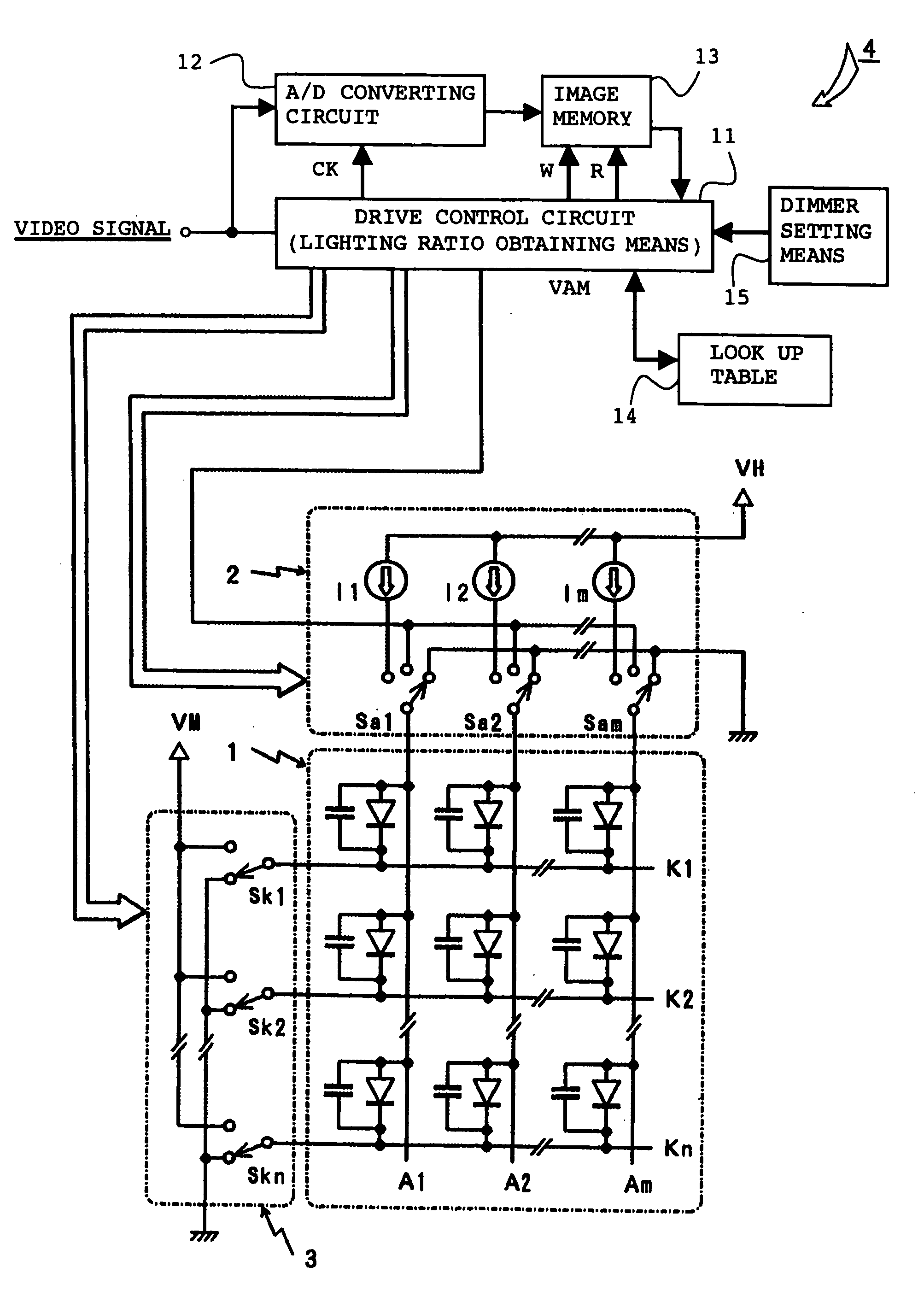
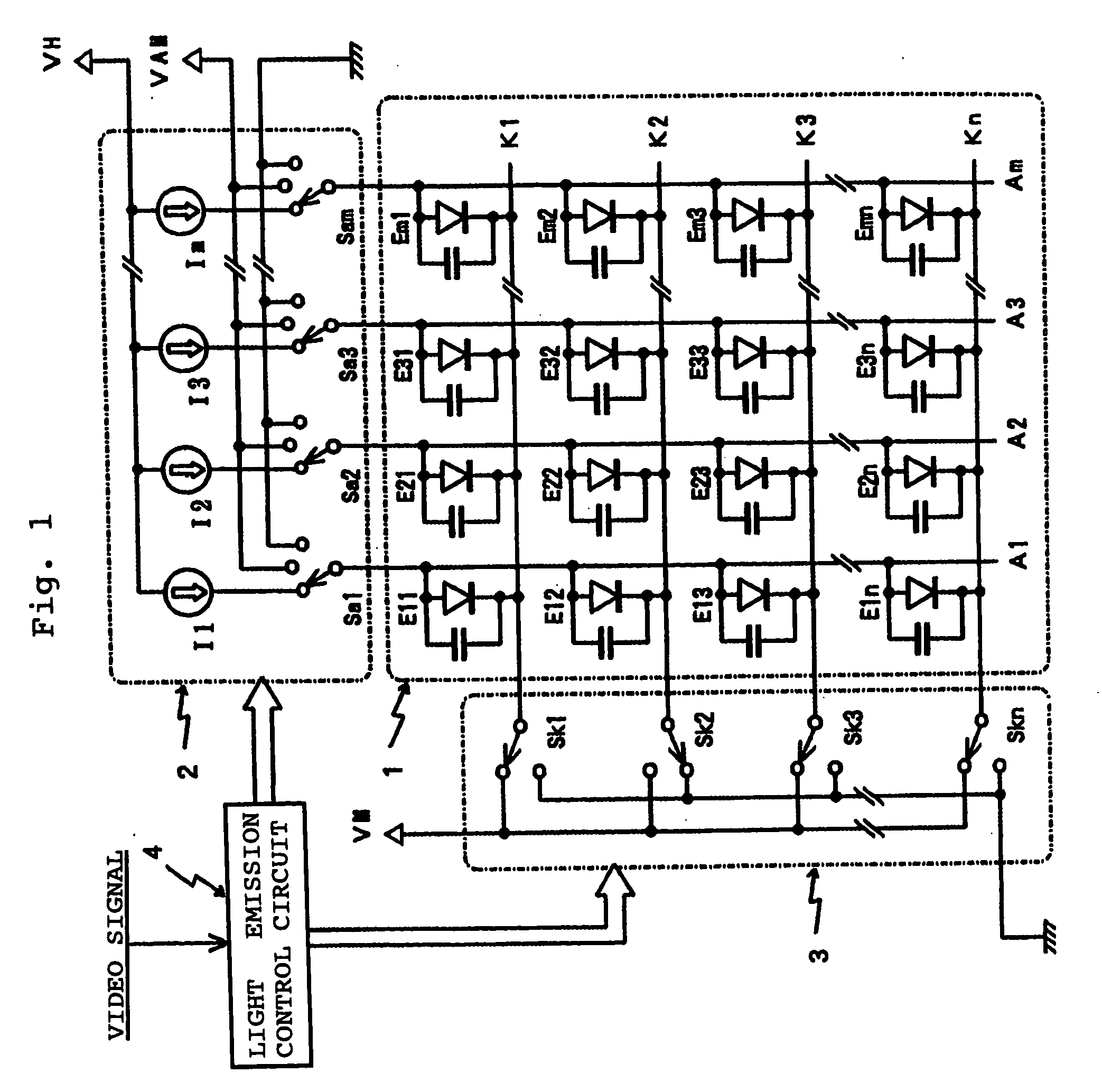
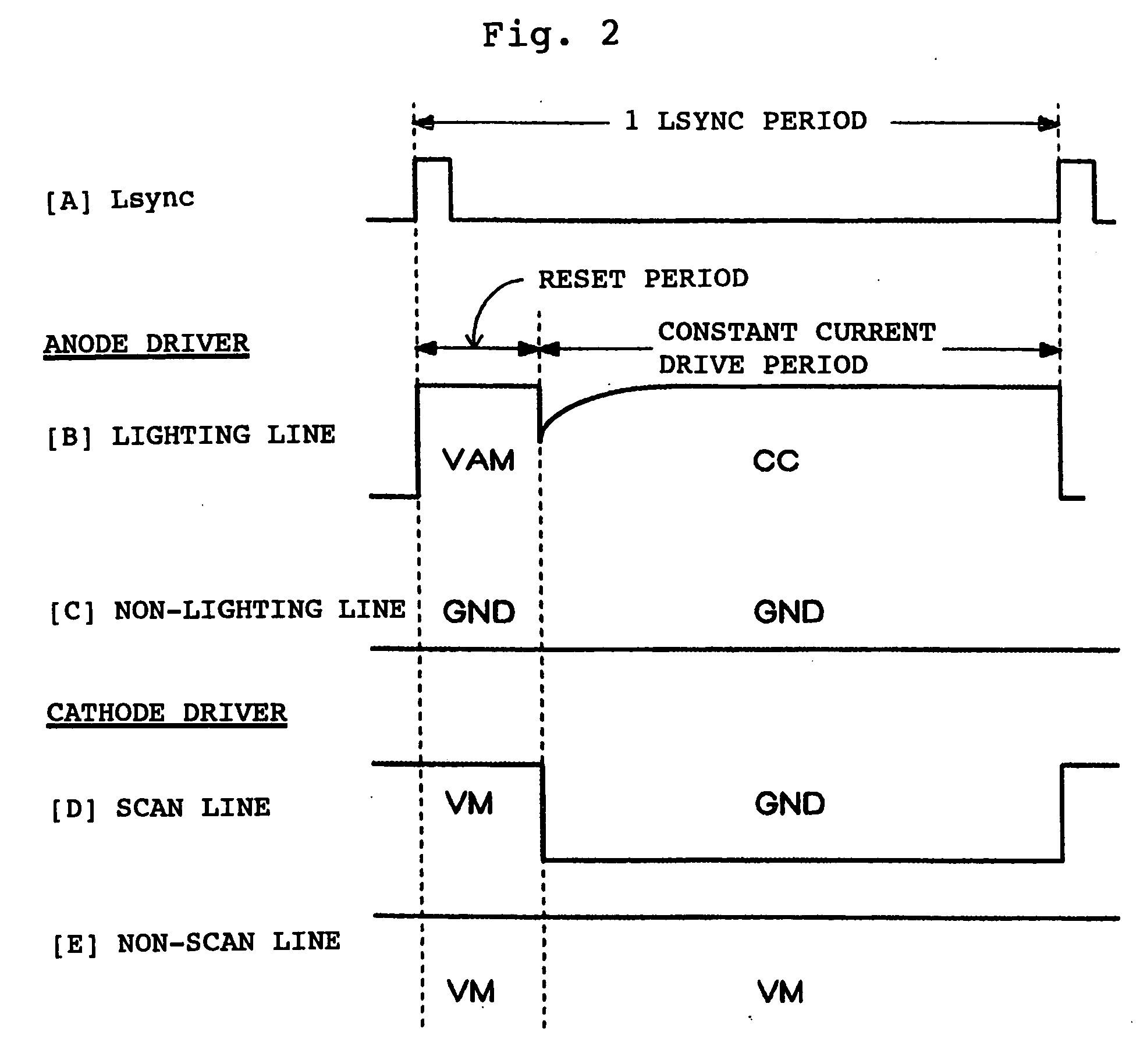
[0052] As a drive device according to the present invention, the same circuit structure as that of shown in FIG. 1 already described is adopted basically. In the drive device according to the present invention, a reset period, a precharge period, and a constant current drive period (lighting period) are set for each one scan period in synchronization with a scan synchronization signal shown in FIG. 6A.

[0053] Timing charts shown in FIG. 6 are shown in an expression similar to that shown in FIG. 2 already described. Respective drive switches Sa1-Sam in a data driver (anode driver) 2 and scan switches Sk1-Skn in a scan driver ...


PUM


Abstract

Provided is a drive device and a drive method of a light emitting display panel in which shadowing generated due to the lighting ratio of light emitting elements and a dimmer setting condition can be reduced to a level at which there is no problem for practical use. An analog video signal is supplied to a drive control circuit 11 and an A/D conversion circuit 12 and is converted into image data which corresponds to each pixel in the A/D conversion circuit 12 to be written in an image memory 13. The image data is read out of the image memory 13 for each scan, and the drive control circuit 11 obtains a rate of EL elements which are to be controlled to emit light (lighting ratio of light emitting elements for each scan). Based on the lighting ratio and dimmer setting data, precharge control data is read out of a look up table 14, and a precharge voltage VAM based on the precharge control data is supplied to a data driver 2. Thus, the precharge amount in the parasitic capacitances of the light emitting elements is changed, and as a result, the occurrence rate of shadowing can be restrained.

Description

BACKGROUND OF THE INVENTION [0001] 1. Field of the Invention [0002] The present invention relates to a drive device and a drive method which can be suitably adopted in a passive matrix type light emitting display panel in which capacitive light emitting elements are employed, and more particularly to a drive device and a drive method of a light emitting display panel in which the occurrence rate of shadowing (horizontal crosstalk) generated due to a change of the lighting ratio of light emitting elements can be reduced to a level at which there is no problem for practical use. [0003] 2. Description of the Related Art [0004] Demand for a display panel which has a high definition image display function and which can realize a thin shape and low power consumption has increased due to popularity of cellular telephones, personal digital assistants (PDAs), and the like, and conventionally a liquid crystal display panel has been adopted in many products as the one which meets the needs the...

Claims


Application Information

Patent Timeline
Patent Type & Authority Applications(United States)
IPC IPC(8): G09G3/32
CPCG09G3/3216G09G3/3266G09G3/3275G09G2310/0251G09G2310/061G09G2320/0209G09G2320/0285G09G2320/0606G09G2320/0626G09G2360/144
Inventor TOGASHI, MASATOAOKI, TOSHIHIKO
Owner TOHOKU PIONEER CORP
Why Eureka
Try Eureka