Polarization element and method of manufacturing polarization element

Active Publication Date: 2013-09-26
SEIKO EPSON CORP
View PDF2 Cites 11 Cited by
  • Summary
  • Abstract
  • Description
  • Claims
  • Application Information

AI Technical Summary

Benefits of technology

[0027]According to this application example, it is possible to realize an electronic device i

Problems solved by technology

However, since a projector obtains a higher brightness year on year, high temperature reliability of an inorganic polarization element which is disposed on a ligh

Method used


Image

  • Polarization element and method of manufacturing polarization element
  • Polarization element and method of manufacturing polarization element
  • Polarization element and method of manufacturing polarization element

Examples


first embodiment

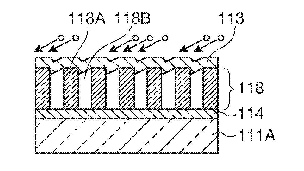
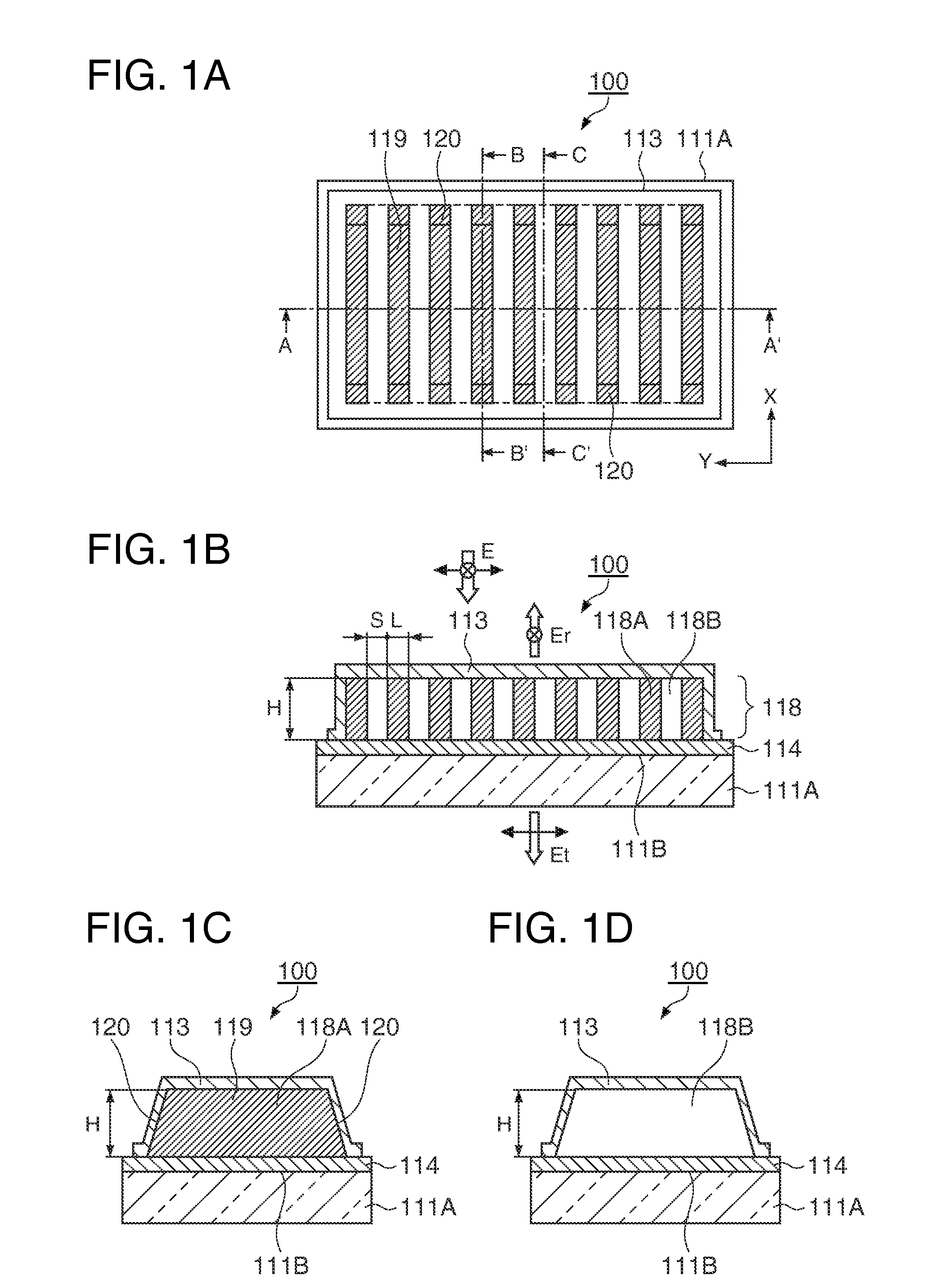
[0038]First, a polarization element 100 of the embodiment will be described with reference to FIGS. 1A to 1D. Herein, FIG. 1A is a plane view showing the polarization element 100 of the embodiment, FIG. 1B is a cross-sectional view taken along a line A-A′ of FIG. 1A and an explanatory diagram of an operation of the polarization element, FIG. 1C is a cross-sectional view taken along a line B-B′ of FIG. 1A, and FIG. 1D is a cross-sectional view taken along a line C-C′ of FIG. 1A.

[0039]As shown in FIGS. 1A to 1D, the polarization element 100 is a light reflective polarization element, and includes a substrate 111A, a wire grid polarization layer 118 formed on a ground layer 114 which covers a surface 111B of the substrate 111A, and a protecting layer 113 which is provided on the surface 111B of the substrate 111A through the wire grid polarization layer 118.

[0040]The substrate 111A is formed of a transparent substrate such as glass, quartz, and plastic, and when the polarization elemen...

second embodiment

Projector

[0065]FIG. 7 is a schematic configuration view showing main parts of a projector 800 including the polarization element according to the first embodiment. The projector 800 of the embodiment is a liquid crystal projector with a liquid crystal light modulating device used as a light modulating device.

[0066]The projector 800 includes a light source 810, a dichroic mirror 813, a dichroic mirror 814, a reflecting mirror 815, a reflecting mirror 816, a reflecting mirror 817, a light entering lens 818, a relay lens 819, a light emitting lens 820, a liquid crystal modulating device for red light 822, a liquid crystal modulating device for green light 823, a liquid crystal modulating device for blue light 824, a cross dichroic prism 825, a projecting lens 826, an entering side polarization element 831, an entering side polarization element 832, an entering side polarization element 833, an emitting side polarization element 834, an emitting side polarization element 835, and an emi...

third embodiment

Electronic Device

[0073]FIG. 8 is a perspective configuration view of a mobile phone which is an example of an electronic device which includes the liquid crystal device including the polarization element according to the first embodiment as a display unit. A mobile phone 1300 includes the liquid crystal device as a small-sized display unit 1301, and includes a plurality of manual operation buttons 1302, an ear piece 1303, and a mouthpiece 1304.

[0074]The liquid crystal device is not limited to being used in the mobile phone, and can suitably be used as an image display unit such as an electronic book, a personal computer, a digital still camera, a liquid crystal television, a view finder type or a monitor direct-view type video tape recorder, a car navigation system, a pager, an electronic notebook, a calculator, a word processor, a workstation, a video phone, a POS terminal, a device including a touch panel, or the like, and it is possible to obtain a high brightness, a high contras...


PUM


Abstract

A polarization element includes a plurality of metallic thin lines that extend in one direction on one surface of a substrate, a protecting layer that is provided on the plurality of metallic thin lines, and a cavity portion that is surrounded by two metallic thin lines which are adjacent to each other, the substrate, and the protecting layer. Each end portion of the plurality of metallic thin layers has a forward tapered shape in a cross-section parallel to the one direction, and the protecting layer extends from the upper portion of the plurality of metallic thin lines to the one surface of the substrate through each end portion.

Description

BACKGROUND[0001]1. Technical Field[0002]The present invention relates to a polarization separating element which is generally called a wire grid polarization element.[0003]2. Related Art[0004]A wire grid polarization element has a configuration in that a grid formed of metal is laid on a transparent substrate. The biggest property of the wire grid polarization element is that the pitch of the grid is sufficiently shorter than a wavelength being used.[0005]Since the wire grid polarization element is configured of only inorganic materials, degradation due to heat does not frequently occur, compared to a polarization element using organic materials. However, since a projector obtains a higher brightness year on year, high temperature reliability of an inorganic polarization element which is disposed on a light path thereof becomes a problem due to an increase in temperatures.[0006]As a result of an investigation, it is determined that degradation in an optical property measured when th...

Claims


Application Information

Patent Timeline
IPC IPC(8): G02B5/30G02F1/1335G03B21/14
CPCG02B5/3058
Inventor AOTA, MASAAKI
Owner SEIKO EPSON CORP
Why Eureka
Try Eureka