Recovery rotational speed for diamond-tipped core drilling devices after a temperature switch-off (overheating of the motor)

a technology of rotating speed and drilling device, which is applied in the direction of manufacturing tools, metal-working machine components, portable power-driven tools, etc., can solve the problems of power tool requiring a cooling period whose duration cannot be determined, power tool is altogether defective, and the cooling period is too soon or too quickly

Inactive Publication Date: 2016-06-30
HILTI AG
View PDF3 Cites 9 Cited by
  • Summary
  • Abstract
  • Description
  • Claims
  • Application Information

AI Technical Summary

Benefits of technology

[0014]According to another advantageous embodiment of the present invention, it can be provided that the threshold value is specified as a function of the ambient temperature around the power tool. This prevents, for instance, that the threshold value is set too low, which would cause it to be exceeded too soon or too quickly.

Problems solved by technology

A drawback of this approach according to the state of the art, however, is that the power tool requires a cooling period whose duration cannot be determined by the user, as a result of which the work with the power tool is interrupted for an indeterminable period of time.
Moreover, when the power tool is switched off suddenly in case of overheating, it might be assumed that the power tool is altogether defective and, even though the power tool would be operational once again after having cooled off, it might be the case that work is not resumed with this assumedly “defective” power tool.
This prevents, for instance, that the threshold value is set too low, which would cause it to be exceeded too soon or too quickly.

Method used


Image

  • Recovery rotational speed for diamond-tipped core drilling devices after a temperature switch-off (overheating of the motor)
  • Recovery rotational speed for diamond-tipped core drilling devices after a temperature switch-off (overheating of the motor)
  • Recovery rotational speed for diamond-tipped core drilling devices after a temperature switch-off (overheating of the motor)

Examples


Embodiment Construction

[0019]Identical components are provided with the same reference numerals in the figures as well as in the description below.

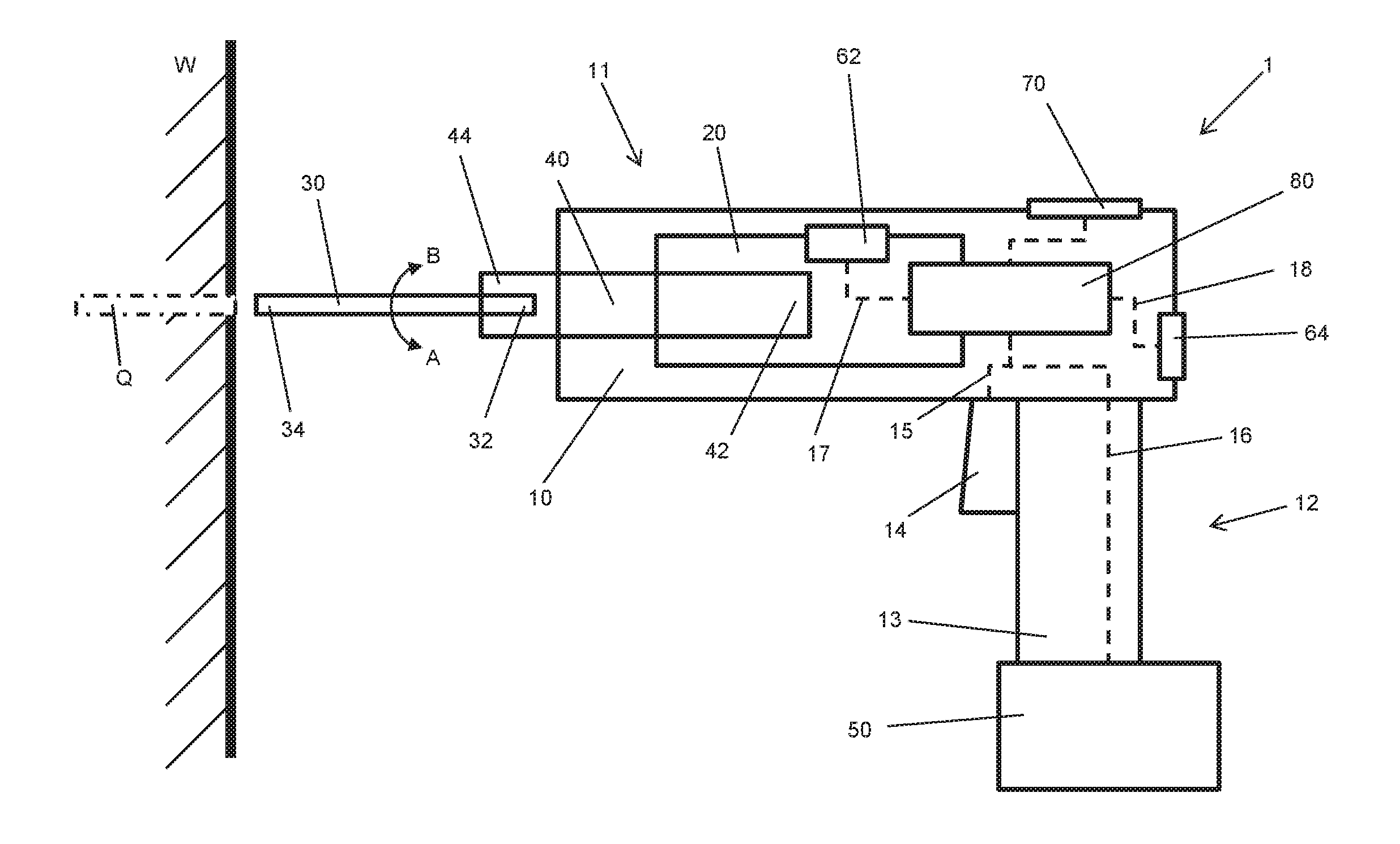
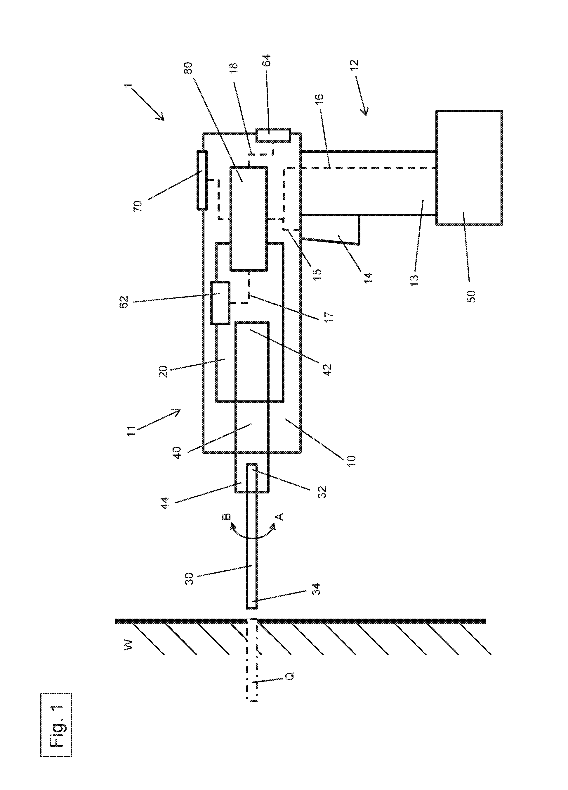
[0020]FIG. 1 shows a power tool 1 comprising a housing 10, a drive 20, a tool 30, a drive shaft 40, an energy source 50, a first temperature sensor 62, a second temperature sensor 64, a data indicator 70 and a control unit 80.

[0021]The housing 10 consists essentially of a first part 11 comprising the drive 20, the first temperature sensor 62, the second temperature sensor 64 and the control unit 80, as well as of a second part 12 comprising a handle 13, a switch 14 and the energy source 50. The switch 14 is connected to the control unit 80 via a line 15 so that the control unit 80 puts the drive 20 into operation when the switch 14 is actuated. Releasing the switch 14 causes the control unit 80 to halt the drive 20. Consequently, the control unit 80 serves primarily to control the drive 20.

[0022]The drive 20 is configured as an electric motor and the tool 30 is...


PUM


Abstract

A method is provided for controlling a power tool (1) when a material (W) is being worked, including the steps:the rotational speed of a drive (20) of the power tool is set to a first value;a first temperature value is measured;the first temperature value is compared to a pre-specified threshold value;the rotational speed of the drive (20) is reduced from the first value to a second value if the first temperature value exceeds the pre-specified threshold value for a pre-specified first period of time;a second temperature value is measured;the second temperature value is compared to the pre-specified threshold value; andthe rotational speed of the drive (20) is raised from the second value to the first value if the second temperature value has fallen below the pre-specified threshold value for a pre-specified second period of time.

Description

[0001]The present invention relates to a method to control a power tool when a material is being worked.BACKGROUND[0002]When a material is being worked by a power tool such as, for example, a hammer drill, a power drill, a circular saw or the like, the power tool can experience a temperature-related failure if it has been in use intensively or for a long time. In order to generate a high torque or a high performance output, the power tool drive, which is normally in the form of an electric motor, requires a high current or voltage from the battery or (depending on the application) from the power network. As a result, the electric motor configured as the drive generates a great deal of heat.[0003]Even though almost all modern electric motors have a cooling means that is designed to protect the electric motor against excessive temperatures and against the possible resultant damage, the cooling capacity of these cooling means is often limited because of the space restrictions in the in...

Claims


Application Information

Patent Timeline
Patent Type & Authority Applications(United States)
IPC IPC(8): B23Q11/14B23Q15/12B25F5/00
CPCB23Q11/14B23Q15/12B25F5/00
Inventor KABZA, FABIANKOSLOWSKI, OLIVERKOENIGBAUER, EGONLIEB, KONRADFORSTNER, MARKUSASMUS, TORSTEN
Owner HILTI AG
Why Eureka
Try Eureka