A method and a system for controlling vehicle speed

a technology of vehicle speed and control method, which is applied in the direction of brake system, vehicle sub-unit features, vehicle components, etc., can solve the problems of increasing the wear rate of brakes, not always being able to maintain the brake set speed, and damage to brakes, so as to improve the comfort of drivers

Active Publication Date: 2018-08-30
VOLVO LASTVAGNAR AB
View PDF5 Cites 12 Cited by
  • Summary
  • Abstract
  • Description
  • Claims
  • Application Information

AI Technical Summary

Benefits of technology

[0006]It is desirable to provide a method and a system for controlling vehicle speed in a vehicle equipped with brake cruise control which eliminates the above problems. The invention allows, according to an aspect thereof, automatic control of the speed of a vehicle requiring a minimum of intervention and providing a high level of comfort for the driver.
[0008]In this context, the term “service brake” is used to denote the normal, or main brakes used in heavy-duty vehicles, usually operated by the driver depressing a service brake pedal. The service brakes are often, but not necessarily, air brakes operated by compressed air controlling friction brakes provided on each wheel to be braked on the vehicle. The term “auxiliary brakes” is used to denote additional means for assisting braking of the vehicle. Auxiliary brakes are used in addition to the service brakes and allow for prolonged brake application without requiring assistance from the service brakes. In this way, wear and unnecessary heating of the service brakes can be avoided. Such auxiliary brakes can comprise an exhaust valve, for activating an exhaust brake, engine brake valves, for activating a compression release engine brake, a fluid retarder, for generating a braking force on a propeller shaft, or means for driving a compressor or generator to generate a braking force. For electric and hybrid electric vehicles the auxiliary brake can comprise a generator, a motor-generator or other suitable means.
[0019]An advantage of this method is that the driver is not required to perform any action, apart from briefly applying the brake pedal, to reduce the speed of the vehicle to a lower brake set speed. No additional switches or controls need to be actuated and no new set speed has to be selected by the driver. A reduction of the manual actions required for this purpose allows the driver to concentrate on the road and improves the driving comfort.
[0025]An advantage of the latter method steps is that the driver is not required to perform any action, or alternatively a single action involving a brief application of the accelerator pedal or actuating one switch, to resume the first brake set speed of the vehicle. No additional switches or controls need to be actuated and no new / earlier set speed has to be selected by the driver. This further reduces the manual actions required, which allows the driver to concentrate on the road and improves the driving comfort.
[0033]By the provision of a method and a system which involve automatic control of a brake cruise control system, the advantage is that the driver can be relieved of a number of the manual actions by transferring control of the brake cruise control system to a control unit. With the brake cruise control system active, the driver merely needs to apply the service brakes to indicate that a speed reduction is desired. When the service brakes are released, the control unit will automatically set the brake set speed to a lower value. This lower value is retained to the end of the downhill road section, or until the driver indicates a further speed reduction. At the end of a downhill section the control unit can be arranged to automatically reset the brake set speed to the initial brake set speed. Alternatively, the driver can indicate that the initial brake set speed is to be reset by issuing a resume command, for instance by actuating a resume switch or by depressing an accelerator pedal. In this way the number of manual actions required by the driver can be reduced to an absolute minimum, allowing the driver to concentrate on the road and improving the comfort for the driver.

Problems solved by technology

When travelling downhill in a vehicle with brake cruise control, it is not always possible to maintain the brake set speed by using auxiliary brakes only.
Extended periods of service brake actuation can cause the brakes to overheat, which can cause the brakes to wear at an increased rate and may even damage the brakes.

Method used


Image

  • A method and a system for controlling vehicle speed
  • A method and a system for controlling vehicle speed
  • A method and a system for controlling vehicle speed

Examples


Embodiment Construction

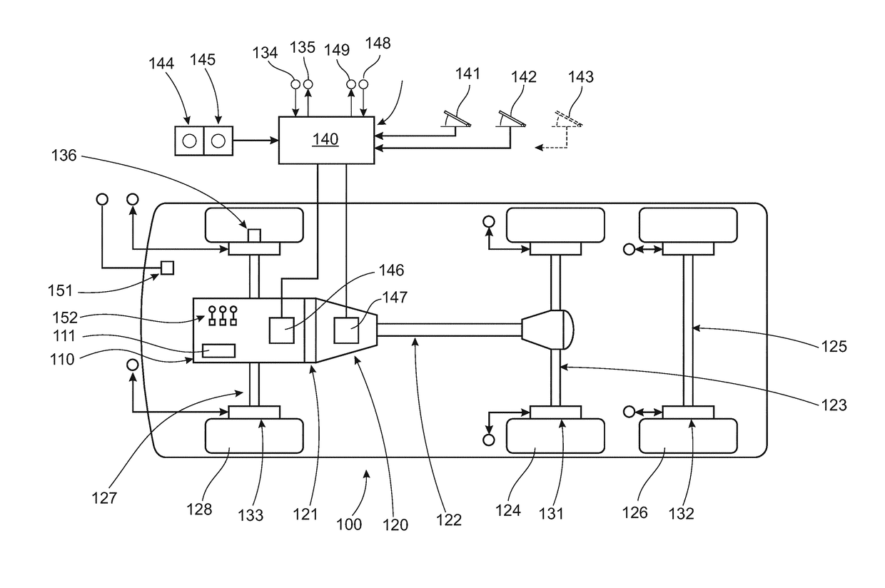
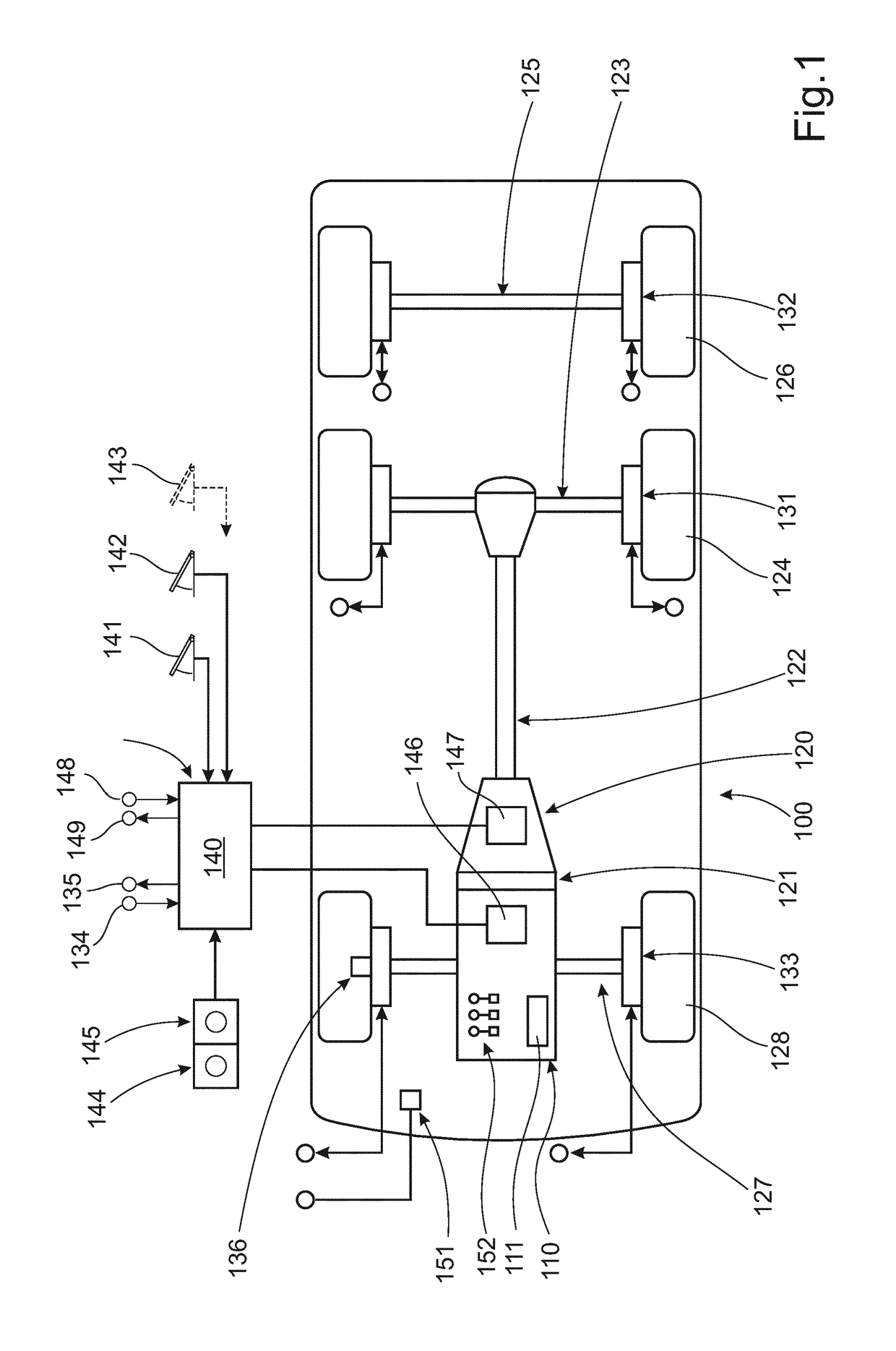
[0041]FIG. 1 shows a schematic vehicle provided with a vehicle speed control system according to one embodiment of the invention. FIG. 1 shows a vehicle 100, such as a tractor of a tractor semi-trailer vehicle, having an electronically controlled internal combustion engine 110 coupled to a transmission 120 via a clutch mechanism 121. It should be noted that a vehicle as shown in FIG. 1 only represents one of the possible applications for the system and method of the present invention. The present invention can be implemented in any type of commercial or industrial vehicle comprising a vehicle speed control system as described herein.

[0042]The transmission 120 can be an automated mechanical transmission or an alternative suitable transmission connected to an output shaft 122 coupled to a driven axle 123 driving a pair of driven wheels 124. The vehicle 100 includes at least two axles such as a steerable axle 127 and at least one rear driven axle 123. FIG. 1 shows a rear driven axle 12...


PUM


Abstract

A device and a method for controlling vehicle speed in a vehicle equipped with brake cruise control when the vehicle is travelling downhill are provided. The method involves driving a vehicle downhill with the brake set speed set to a first brake set speed; detecting a current vehicle speed; automatically applying a brake torque using at least an auxiliary brake to maintain the first brake set speed; and detecting a manual application of a vehicle service brake, in order to decrease vehicle speed. If a control unit detects that the driver is applying the service brake, then the control unit is automatically arranged to set the brake set speed to a second brake set speed that is lower than the first brake set speed; and to apply a brake torque using at least the auxiliary brake if a detected current vehicle speed exceeds the second brake set speed.

Description

BACKGROUND AND SUMMARY[0001]The invention relates to a method and a system for controlling vehicle speed in a vehicle equipped with brake cruise control when the vehicle is travelling downhill. The invention can be applied in heavy-duty vehicles, such as trucks, buses and construction equipment. Although the invention will be described with respect to a heavy-duty vehicle, the invention is not restricted to this particular vehicle, but may also be used in other vehicles such as articulated haulers, wheel loaders, and other working machines or automobiles.[0002]Driver assistance systems for automatically controlling the speed of a vehicle, often termed cruise control systems, allow a driver to specify a selectable driving speed via actuating means. The set speed is then maintained independently of the operation of an accelerator pedal of the vehicle. The speed can be set by the driver and can also be retained independently of the driving situation, such as uphill or downhill driving....

Claims


Application Information

Patent Timeline
Patent Type & Authority Applications(United States)
IPC IPC(8): B60T8/17B60T8/171B60T8/172B60T8/24B60T8/32
CPCB60T8/1708B60T8/171B60T8/172B60T8/245B60T8/323B60Y2200/145B60Y2200/148B60Y2300/146B60Y2400/303B60Y2300/43B60T2201/04B60T2201/02B60T2250/04B60W30/143B60T7/12
Inventor CARLSSON, TOBIASERIKSSON, ANDERSKARLSSON, LARSANDERSSON, HENRIK
Owner VOLVO LASTVAGNAR AB
Why Eureka
Try Eureka