Marine engine assembly including a pod mountable under a ship's hull

a technology of engine and hull, which is applied in the field of marine propulsion sets with pods, can solve the problems of reducing the performance of the propulsion set, affecting the performance of the set, so as to reduce the diameter of the pod and the weight of the set, reduce the diameter of the motor or engine, and reduce the effect of the diameter of the pod

Active Publication Date: 2013-05-07
ALSTOM SA
View PDF19 Cites 9 Cited by
  • Summary
  • Abstract
  • Description
  • Claims
  • Application Information

AI Technical Summary

Benefits of technology

[0020]The arrangement formed by the fins and the nozzle constitutes the stator of the screw pump. A screw pump generally rotates 50% to 100% faster than a conventional propeller of equivalent power, which makes it possible to reduce by 50% to 100% the torque of the drive motor or engine for the propeller and thus allows the diameter of the motor or engine to be reduced by from 20% to 40% (for an electric motor) relative to a conventional pivotally mounted pod set. In a propulsion set of the invention, the reduction in the diameter of the motor makes it possible to reduce the diameter of the pod and the weight of the set for embodiments in which the motor is housed inside the pod. The reduction in the diameter of the pod makes it possible to reduce the hydrodynamic drag of the propulsion set and thus to increase its propulsive efficiency.
[0021]In addition, the motor and most of the volume of the pod are situated upstream from the screw pump relative to the flow of water. This makes it possible for the propeller to have a hub that is relatively compact, and a sectional area can thus be obtained for the propeller of the pump that is sufficient without it being necessary to degrade hydrodynamic flow by increasing the diameter of the nozzle to an exaggerated extent. Typically, with an electric motor having power greater than 10 MW housed inside the pod, a propulsion set of the invention can be obtained with a nozzle whose inside diameter, i.e. substantially the diameter of the propeller, is about twice the diameter of the pod. This makes it possible to have a sectional area for the propeller that is sufficient to guarantee a good flow-rate of water through the pump, while also having hydrodynamic drag for the propulsion set that is relatively low compared with the apparatus of Patent DE 101 58320.
[0022]Finally, the fact that it is possible for the screw pump to work in the ship's wake without any cavitation phenomenon makes it possible to reduce the height of the support strut, thereby also contributing to making the set more compact. The screw pump can be brought closer to the hull of the ship because it does not transmit any pressure pulses generating vibration on board the ship. This can be explained firstly by the fact that the flow of water is organized by the stator of the screw pump, which makes it possible for the speed of arrival of the water at the rotor to be made uniform in the chamber that separates the rotor from the stator. The residual pressure pulses generated by the screw pump are therefore relatively small. In addition, said residual pulses are attenuated at the nozzle of the pump, and their repercussion on the hull of the ship is sufficiently low not to generate vibration on board the ship.
[0023]The draught under the hull can then be smaller than with a conventional pivotally mounted pod set, which makes it possible to have greater flexibility for designing stern shapes for a ship. In addition, the fact that the screw pump is placed inside the boundary layer of the ship's wake offers the advantage of increasing its propulsive efficiency relative to the propulsive efficiency procured with the screw pump disposed outside the boundary layer. Inside said boundary layer, the speed of the water at the inlet of the screw pump is reduced relative to said speed with a configuration in which the screw pump is disposed outside said layer, which increases the differential between the speeds respectively at the outlet of the nozzle and at the inlet of the pump, thereby increasing the thrust generated by the rotor of the pump. It should be noted that the thickness of the boundary layer increases with increasing ship speed and ship size. At the cruising speed of the ship, the magnitude of the wake is greater, and its propulsive efficiency is thus increased relative to its propulsive efficiency at lower speeds.

Problems solved by technology

Generally, conventional marine propulsion sets of the pivotally mounted pod type are not designed to work in the wake of the ship and indeed have a support strut that is long enough for its propeller to be situated outside the boundary layer of the wake.
Such conventional pivotally mounted pod type propulsion sets are generally voluminous at least due to the large amount of space necessary between the hull of the ship and the propeller of the set.
Furthermore, such propulsion sets are generally subjected to vibration and cavitation phenomena, cavitation being particularly present when the propulsion set is slewing.
In marine hydrodynamics, cavitation degrades the performance of propulsive systems, induces vibration, causes erosion of the rotary portions, and radiates noise that degrades the acoustic discreetness of the ship.
Although such a pivotally mounted propulsion pod is particularly compact, the overall propulsion set including the main screw remains voluminous and requires a relatively deep draught under the hull as do conventional pivotally mounted pod type propulsion sets.

Method used


Image

  • Marine engine assembly including a pod mountable under a ship's hull
  • Marine engine assembly including a pod mountable under a ship's hull
  • Marine engine assembly including a pod mountable under a ship's hull

Examples


Embodiment Construction

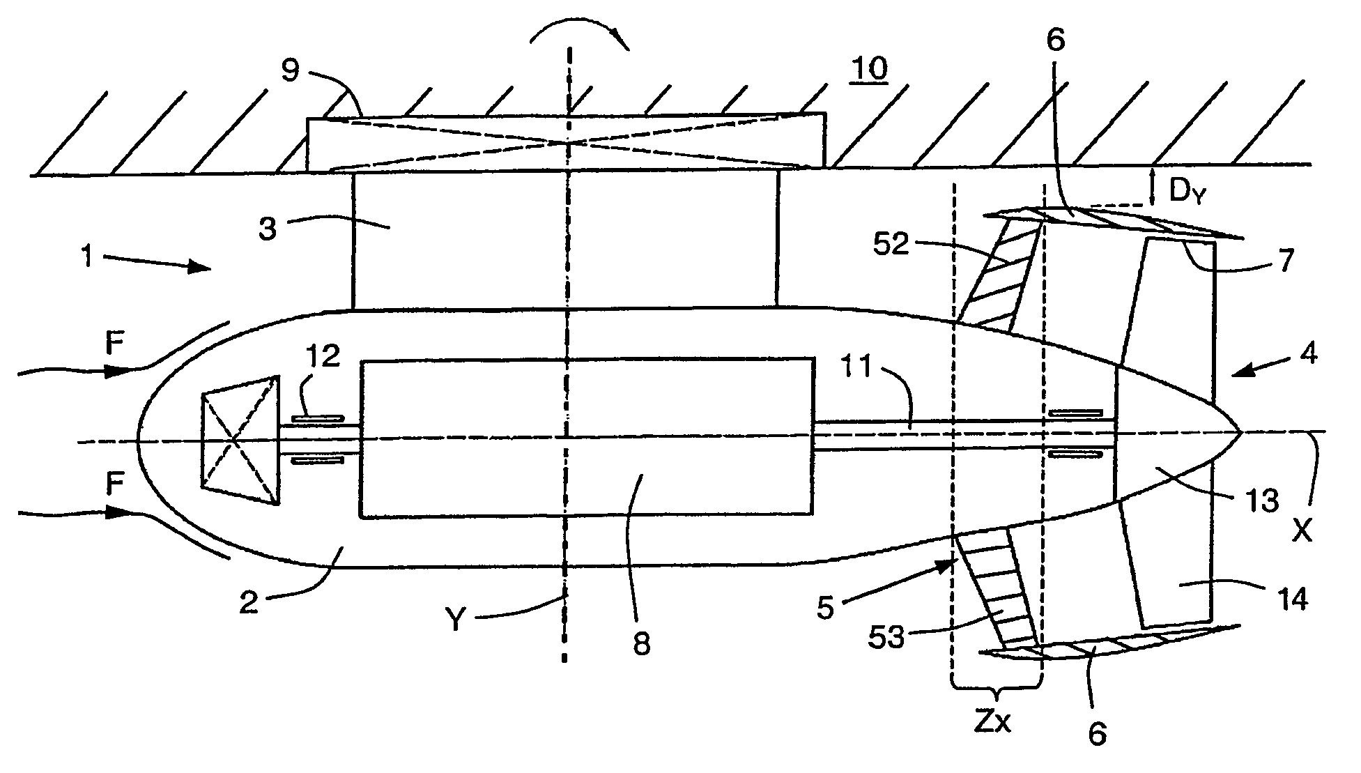
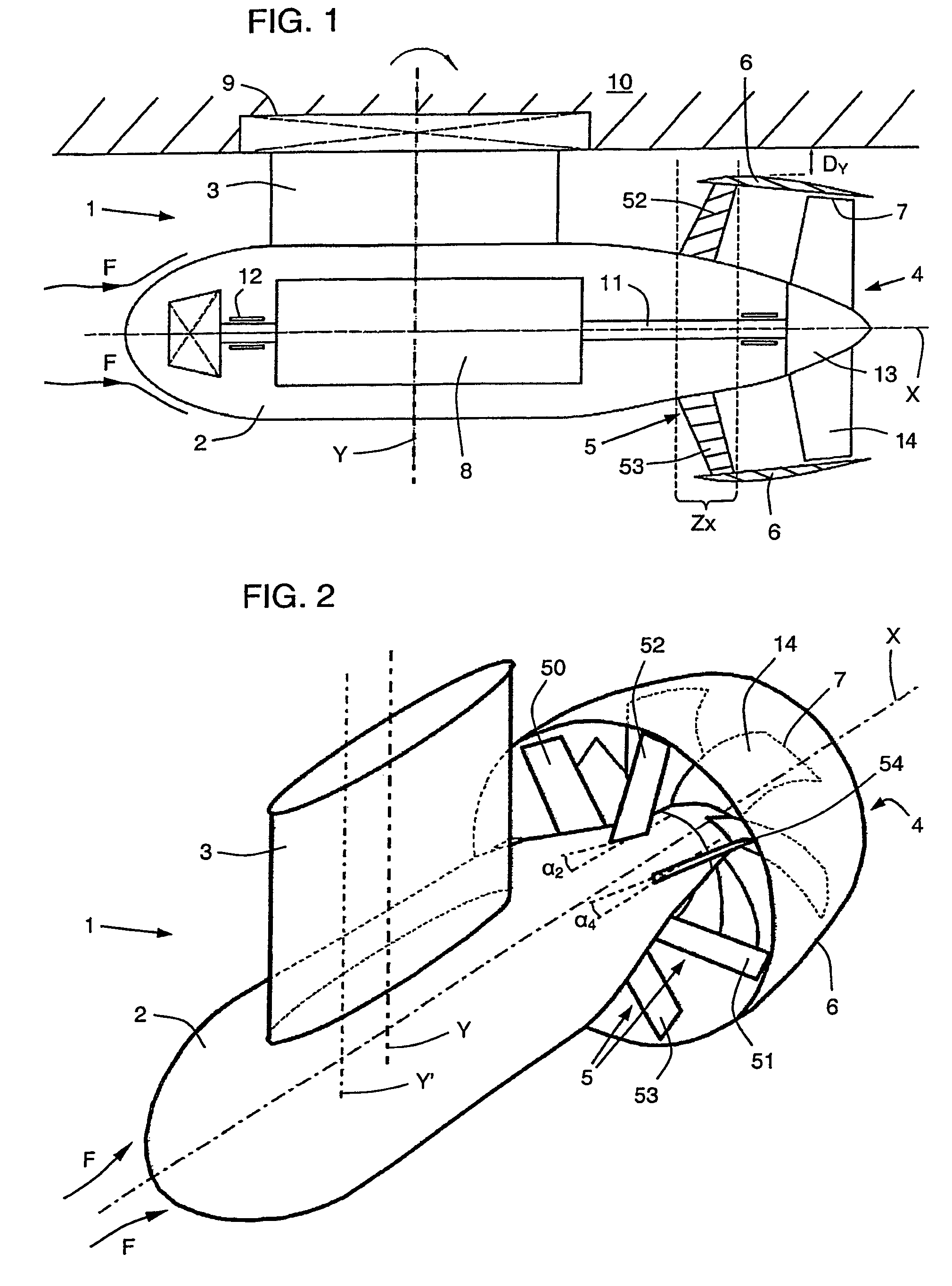
[0031]FIG. 1 shows a propulsion set 1 of the invention seen from the side in longitudinal section on the plane formed by the longitudinal axis X of the pod 2 and by the pivot axis 6 of the set 1. Said set 1 is installed under the hull 10 of a ship, the pod 2 being conventionally connected to a support strut 3 mounted to pivot on a watertight bearing 9 passing through the hull of the ship. In the preferred embodiment shown in the figure, the pod 2 is dimensioned to contain an electric motor 8 whose rotor (not shown) is constrained to rotate with the drive shaft 11 of the propeller 4. The shaft 11 is held on the axis X by means of bearings 12. In known manner, the pod and the support strut 3 are streamlined so as to optimize the hydrodynamic flow of the flow of water represented by the arrows F. FIG. 1 includes a fragmentary structure 10 representing the hull of a conventional ship which includes but does not show fore and aft ends and a central longitudinal axis of such ship.

[0032]As...


PUM


Abstract

The marine propulsion set (1, 1′, 1″) comprises: at least one pod (2) that is mechanically connected to a support strut (3, 3′, 3″); a propeller (4) that is situated at the aft end of the pod and that has at least two blades (14); and an arrangement of at least three flow-directing fins (50 to 55, 3′A) that are fastened to the pod (2). This arrangement of fins forms a ring (5) that is substantially perpendicular to the longitudinal axis (X) of the pod (2), said ring lying within a zone (Zx) that is situated between the central portion of said support strut (3, 3′, 3″) and the propeller. The propulsion set further comprises a nozzle (6) that surrounds, at least in part, the propeller (4) and said ring (5). Each of said blades (14) presents an end with an edge (7) coming flush with the inside wall of the nozzle (6) so that the propeller (4) constitutes the rotor of a screw pump.

Description

I. CROSS-REFERENCE TO RELATED APPLICATIONS[0001]Priority is claimed under 35 U.S.C. §119, 120 and / or 365 on International Application No. PCT / FR 2005 / 050280 having International filing date 26 Apr. 2005 and FR 0450842 with priority date 30 Apr. 2004.II. BACKGROUND OF THE INVENTION[0002]A. Field of the Invention[0003]The invention relates to a marine propulsion set with a pod installable under the hull of a ship.[0004]B. Description of Related Art[0005]Generally, conventional marine propulsion sets of the pivotally mounted pod type are not designed to work in the wake of the ship and indeed have a support strut that is long enough for its propeller to be situated outside the boundary layer of the wake. Such conventional pivotally mounted pod type propulsion sets are generally voluminous at least due to the large amount of space necessary between the hull of the ship and the propeller of the set. Furthermore, such propulsion sets are generally subjected to vibration and cavitation phe...

Claims


Application Information

Patent Timeline
Patent Type & Authority Patents(United States)
IPC IPC(8): B63H5/15B63H5/125B63H5/14
CPCB63H5/14B63H5/125B63H2005/1258B63H5/07
Inventor GAUDIN, CHRISTIAN
Owner ALSTOM SA
Why Eureka
Try Eureka