Combinable floor plate

a floor plate and comb technology, applied in the direction of walls, constructions, building components, etc., can solve the problems of floor damage, insufficient connection between two adjacent floor plates (b>30/b>), and insufficient strength to avoid warping of floor plates

Inactive Publication Date: 2006-08-17
YANG FENG LING
View PDF4 Cites 55 Cited by
  • Summary
  • Abstract
  • Description
  • Claims
  • Application Information

AI Technical Summary

Problems solved by technology

This kind of connection between two adjacent floor plates (30) is not strong enough to avoid warping of the floor plate due to humidity.
That is, when the floor plate gradually warps as a result of humidity seeping into the floor plate, the floor is thus damaged.

Method used


Image

  • Combinable floor plate
  • Combinable floor plate
  • Combinable floor plate

Examples


Embodiment Construction

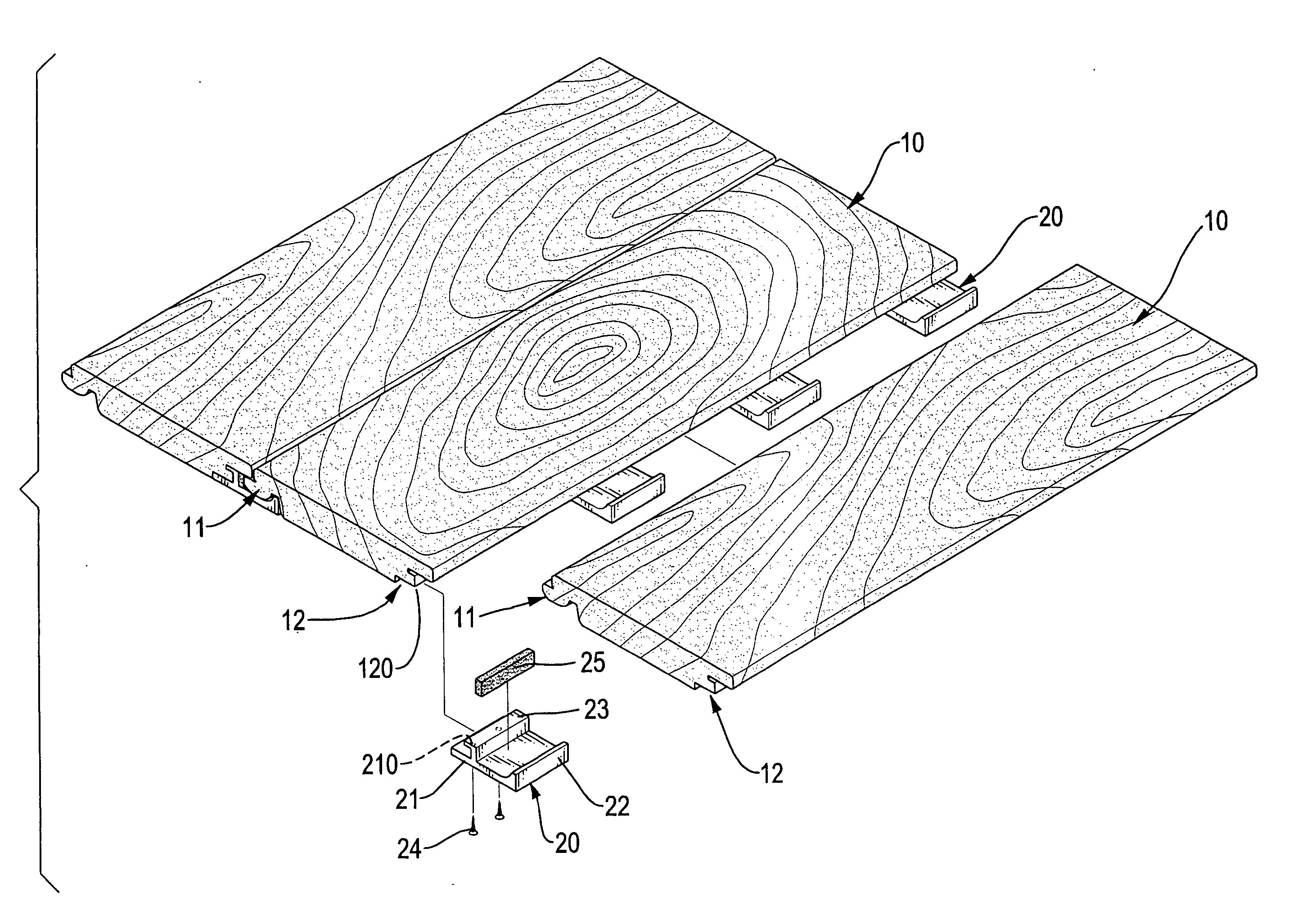
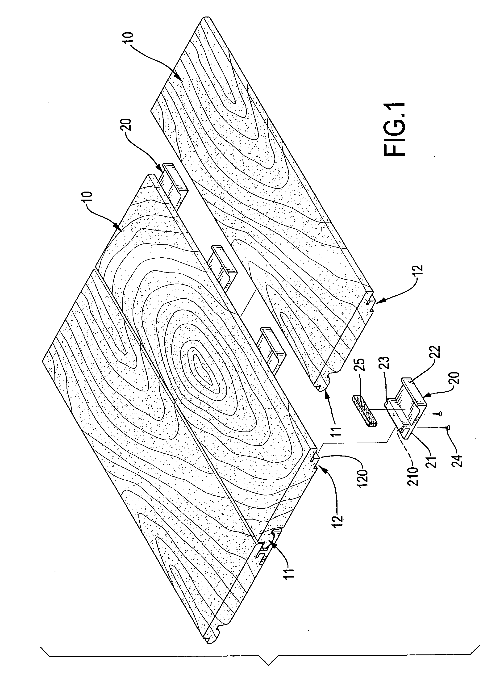
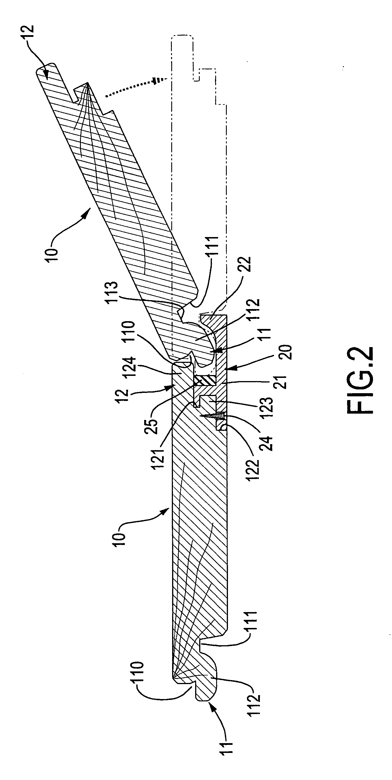
[0015] With reference to FIGS. 1 and 2, it is noted that the floor plate (10) constructed in accordance with the present invention includes a first connection part (11) formed on a first side face of the floor plate (10) and a second connection part (12) formed on a second side face of the floor plate (10) opposite to the first connection part (11).

[0016] The first connection part (11) has a tongue (112) extending from the first side face, an upper cutout (110) defined in a top face of the tongue (112) and a lower cutout (111) defined in a bottom face of the tongue (112). A recess (113) is further defined in a face defining the lower cutout (111) to communicate with the lower cutout (111). The second connection part (12) is defined with a receiving space (120) defined in the second side face of the floor plate (10) to correspond to the tongue (112), a first slit (121) defined in a side face defining the receiving space (120) and a second slit (122) defined in the side defining the ...


PUM


Abstract

A combinable floor plate includes a first connection part formed on a first side face of the floor plate and a second connection part formed on a second side face of the floor plate opposite to the first side face. The first connection part has a tongue and the second connection part is provided with a first extension and a second extension to be respectively received in an upper cutout and a lower cutout in the first connection part. A securing device is to secure engagement between two adjacent floor plates.

Description

BACKGROUND OF THE INVENTION [0001] 1. Field of the Invention [0002] The present invention relates to a combinable floor plate, and more particularly to a combinable floor plate in combination with a securing device to combine two adjacent floor plates. [0003] 2. Description of Related Art [0004] Conventionally, combinable floor plates are pieced together via applying adhesive agent on bottom faces of the floor plates to allow the floor plates to securely engage with a surface, i.e. ground. Further, securing elements such as nails are applied to enhance the engagement of the floor plates to the ground. [0005] A kind of conventional floor plate (30) is shown in FIG. 4. The floor plate (30) has a groove (31) defined in a side of the floor plate (30) and a tongue (32) formed on a side of the floor plate (30) to be opposite and complementary to the groove (31). Thus after adhesive agent is applied to a bottom side of one of the floor plates (30) and the floor plate (30) with adhesive age...

Claims


Application Information

Patent Timeline
Patent Type & Authority Applications(United States)
IPC IPC(8): E04B2/00
CPCE04F15/02E04F15/04E04F2201/0153E04F2201/023E04F2201/042E04F2201/0517
Inventor YANG, FENG-LING
Owner YANG FENG LING
Why Eureka
Try Eureka