

Easily fixable roman blind
- Summary
- Abstract
- Description
- Claims
- Application Information
AI Technical Summary
Problems solved by technology
Method used
Image

Examples
first embodiment
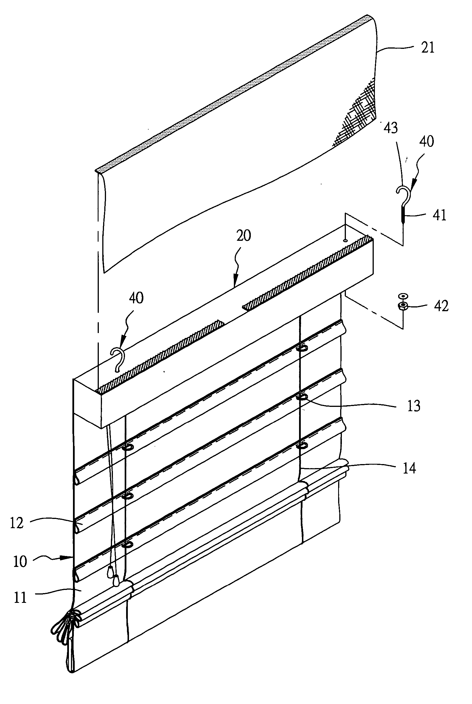
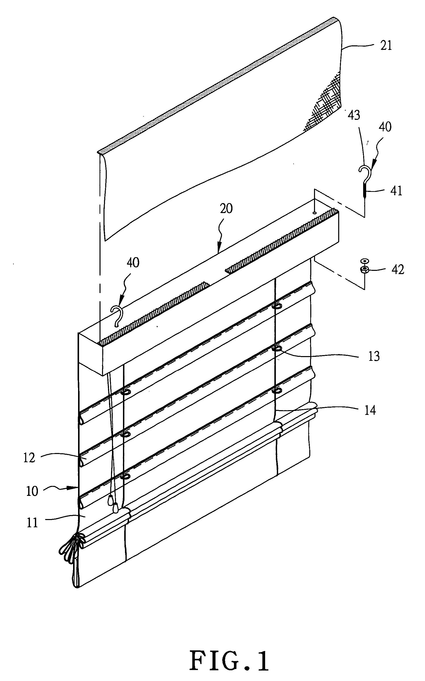
[0022] an easily fixable Roman blind in the present invention, as shown in FIGS. 1 and 2, includes a blind body 10, an upper support member 20, a hanging rod 30, and three movable hangers 40 as main components.
[0023] The blind body 10 is composed of a blind cloth 11, plural of lateral folded members 12 formed spaced apart equidistantly on the back of the blind cloth 11 from the upper side to the lower side, plural rope loops 13 attached spaced apart on each folded member 12, a pull rope 14 provided to have its lower end bound on the lower rod and then extend up to the upper side into the upper support member 20 and then exit out of one of its ends for a user to pull for handling the blind in closing and opening in various extents.
[0024] The upper support member 20 is fixed with an upper end of the blind cloth 11 of the blind body 10, a soft decorative sheet 21 made of cloth removably adhered on a rear side of the upper support member 20 and then extending upward to bend forward to ...
second embodiment
[0029] Next, FIGS. 4, 5 and 6 show a movable hangers 40, which is composed of a fixing ring 44 and a clamping member 45 connecting with the fixing ring 44.
[0030] The clamping member 45 has a clamping body 451 with two symmetrical a little curved portions pivotally connected with each other, and a handle 452 connected with and extending down from the pivot point of the clamping body 451, with a torque spring 453 sandwiched between two portions of the handle 452 for normally pushing outward the two portions of the handle 452 and tightening inward the clamping body 451 accordingly owing to the pivotal point.
[0031] If the two handles 452 are gripped inward, the clamping member 451 is pivotally moved outward to open upper portions 454 of the clamping member 451 so the hanging rod 30 may be inserted in the hollow interior of the clamping member 451. Then when the two handles 452 are released with the compressed torque spring expanding, the upper portions 454 of the clamping member 451 ma...
third embodiment
[0033] Further, FIGS. 7 and 8 show a hanger 40, which is a fixing rope 40 having one of its ends fixed on the upper support member 20, and the other end connected with a fixing rope bound on the hanging rod 30. The fixing rope 40 has a bigger end 46 than the rope itself, and the other end formed with two free ends 461 for binding on the hanging rod 30. Besides, as shown in FIG. 9, the two free ends 461 can be substituted by a hook 462 fixed on one of the ends 461 and a ring 463 fixed on the other end 461 for hooking with each other for hanging on the hanging rod 30.
[0034] Moreover, as shown in FIGS. 10 and 11, the fixing rope 40 can be a rope with a proper length, having two free ends 461 respectively provided with a hook 464, and the upper support member 20 is provided with plural fixing rings 465 fixed on its upper surface, so the fixing rope 40 may be secured by the hooks 464 hooking with two outermost rings 465, and also passing through the intermediate rings 465 and further aro...
PUM
 Abstract
Description
Claims
Application Information