Dual bimorph synthetic pulsator

a synthetic pulsator and bimorph technology, applied in the direction of automatic actuation, valve construction, air-flow influencer, etc., can solve the problems of flow affecting efficiency, poor performance and/or stalling of aircraft engines, and the effect of buffering and fatigue of downstream structures

Inactive Publication Date: 2006-12-07
LOCKHEED MARTIN CORP
View PDF6 Cites 41 Cited by
  • Summary
  • Abstract
  • Description
  • Claims
  • Application Information

AI Technical Summary

Benefits of technology

[0012] Additional embodiments may further couple the synthetic jet to a control system wherein the amplitude and frequency of the oscillatory flow can be controlled. This allows the pulsed jet to impart high amplitude high frequency eddies to the fluid flow in a controlled manner.

Problems solved by technology

Adverse (pressure gradient) fluid flows generated over aerodynamic surfaces can buffet and fatigue any downstream structures so exposed.
Additionally, such flows can affect efficiency by increasing drag or resistance over the surface.
Additionally, these adverse fluid flows can be ingested within engine air intakes or other like air inlets leading to poor performance and / or stalling of the aircraft engines.
Stalling the aircraft engine creates a potentially hazardous condition.
Additionally, exotic aperture shapes for the inlet and outlet may cause excessive propulsion performance losses.
Placing components, such as engines or control surfaces, in non-optimal positions in order to reduce these stresses often results in reduced vehicle performance.
Similarly, adding structural weight to support increased stress loads caused by the flow field vortices also results in reduced vehicle performance.
However, these control flows create a need for compressed air and piping to bring the control jets to regions requiring flow-control authority.
This solution also adds structural weight to supply and support the control jets that result in reduced vehicle performance.
However, these devices have relatively limited capacity, in that they use only a single moving element or a moving element of limited deflection.
Although high-amplitude high-frequency jets may be created synthetically, application of these devices has been restricted due to the inability to create supersonic jets and also operate in hot-gas environments (>500-deg F.).

Method used


Image

  • Dual bimorph synthetic pulsator
  • Dual bimorph synthetic pulsator
  • Dual bimorph synthetic pulsator

Examples


Embodiment Construction

[0031] Preferred embodiments of the present invention are illustrated in the figures like numerals being used to refer to like and corresponding parts of the various drawings.

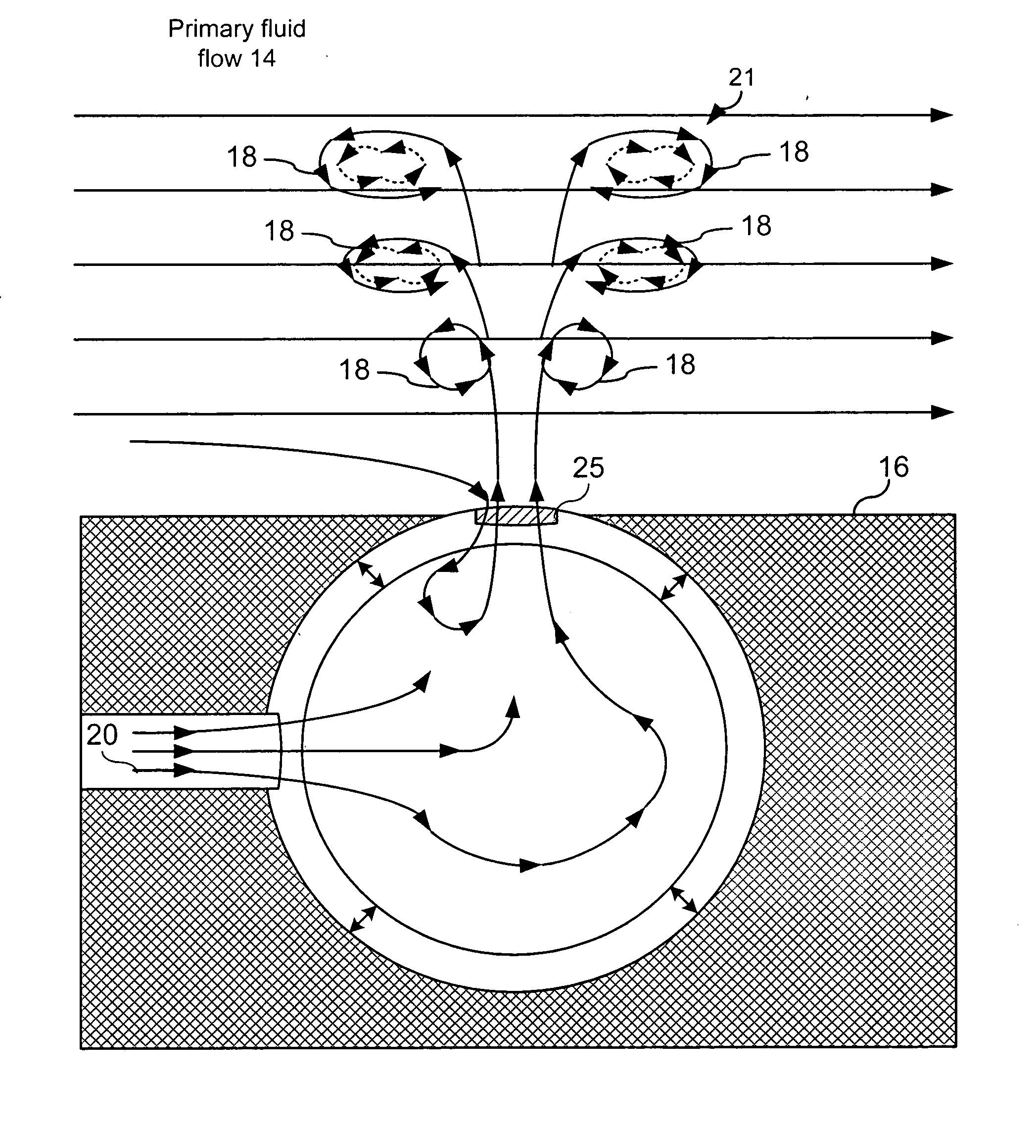
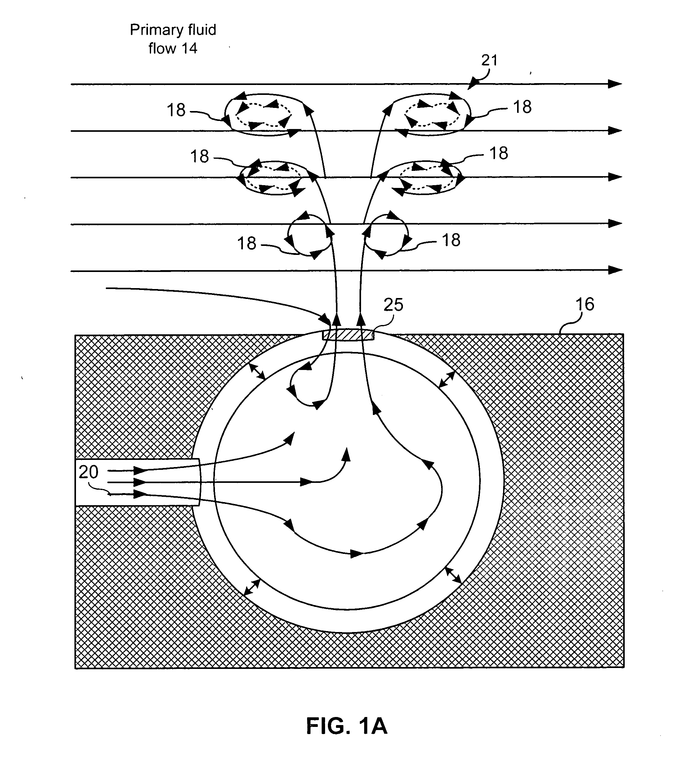
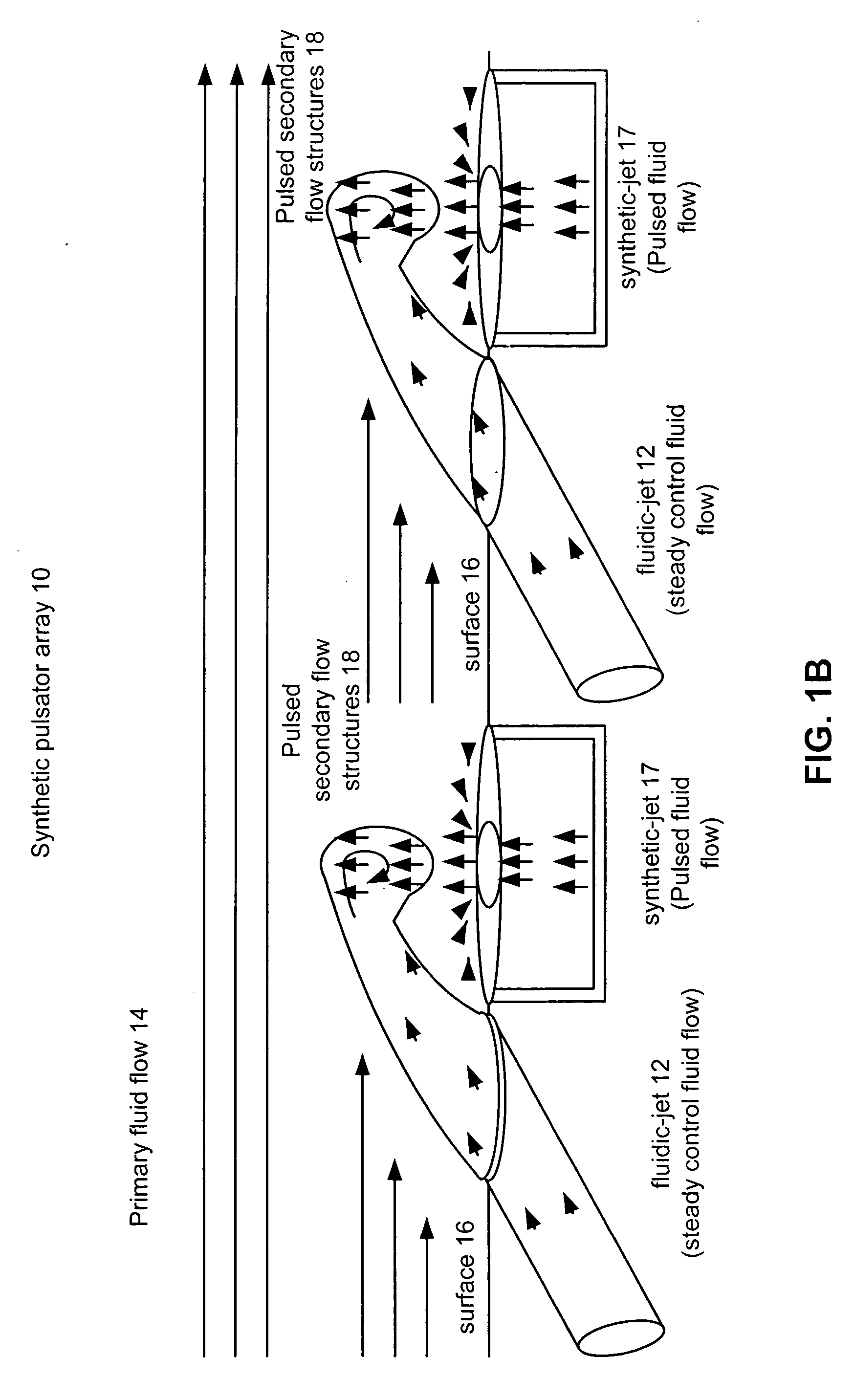
[0032] The present invention provides a system and method for manipulating aerodynamic or hydrodynamic fluid flow over a surface that substantially eliminates or reduces disadvantages and problems associated with previously developed systems and methods. More specifically, the present invention provides a system and method to manipulate flow fields with a synthetic pulsator that combines a steady fluid flow and a pulsed fluid flow provided by synthetic jet. Embodiments of the present invention may place arrays of such pulsators on surfaces bounding the fluid flow. These effectors may be operable to manipulate the flow behavior of the fluid flow, influence the inception point, size, and trajectory of flow field vortices within the fluid flow, and reduce flow separation within the primary fluid flow.

[0033]FIG. ...


PUM


Abstract

The present invention provides a system and method for actively manipulating fluid flow over a surface using synthetic pulsators. Synthetic pulsators produce pulsed jet operable to manipulate the primary fluid flow proximate to the synthetic pulsator. The synthetic pulsator includes a synthetic jet actuator(s) operable to produce an oscillatory flow, and fluidic jet(s) operable to provide a continuous fluid flow. The oscillatory flow of the synthetic jet(s) and the continuous fluid flow of the fluidic jet(s) combine or mix to produce the pulsed jet operable to manipulate the primary fluid flow. These synthetic pulsators may then be actively manipulated to control the flow behavior of the ducted fluid flow, influence the inception point and trajectory of flow field vortices within the fluid flow, and reduce flow separation within the primary fluid flow.

Description

TECHNICAL FIELD OF THE INVENTION [0001] The present invention relates generally to manipulation of fluid flows and more particularly, a system and method for manipulating fluid flows with active synthetic jets operable to pulse steady control fluid flows. BACKGROUND OF THE INVENTION [0002] Adverse (pressure gradient) fluid flows generated over aerodynamic surfaces can buffet and fatigue any downstream structures so exposed. Additionally, such flows can affect efficiency by increasing drag or resistance over the surface. Such adverse fluid flows can be generated at the fore body of an aircraft or other upstream structure, and damage control surfaces, engines, after body / empennage, nacelles, turrets, or other structures integrated into the airframe. Additionally, these adverse fluid flows can be ingested within engine air intakes or other like air inlets leading to poor performance and / or stalling of the aircraft engines. Stalling the aircraft engine creates a potentially hazardous co...

Claims


Application Information

Patent Timeline
Patent Type & Authority Applications(United States)
IPC IPC(8): B05B1/08
CPCB05B1/08B64C21/04B64C2230/18F15D1/12Y02T50/166B64C21/08Y02T50/10
Inventor SADDOUGHI, SEYEDBOESPFLUG, MATTHEWDONNELLY, SCOTT
Owner LOCKHEED MARTIN CORP
Why Eureka
Try Eureka