Two piece design for coordinate loop hanger

Inactive Publication Date: 2006-12-14
PROSPERITY PROD HK LTD
View PDF30 Cites 24 Cited by
  • Summary
  • Abstract
  • Description
  • Claims
  • Application Information

AI Technical Summary

Benefits of technology

[0020] In a more specific aspect of the invention, the first mating profile and second mating profile are a plug and socket (or vice versa). The plug is sized and dimensioned to be received within the socket. The plug and socket can be located interchangeably between the hanger body and ganging element. The skilled artisan would recognize, however, various embodiments to establish s

Problems solved by technology

The drawbacks in such display methods are that in the first example some frame or support is required to display the garments toget

Method used


Image

  • Two piece design for coordinate loop hanger
  • Two piece design for coordinate loop hanger
  • Two piece design for coordinate loop hanger

Examples


Embodiment Construction

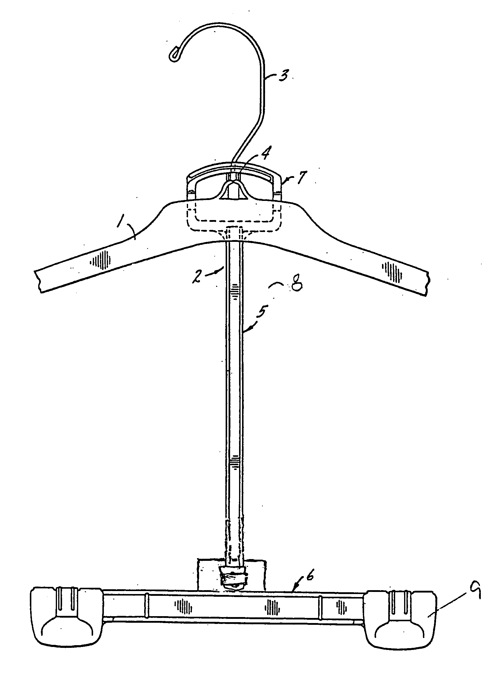
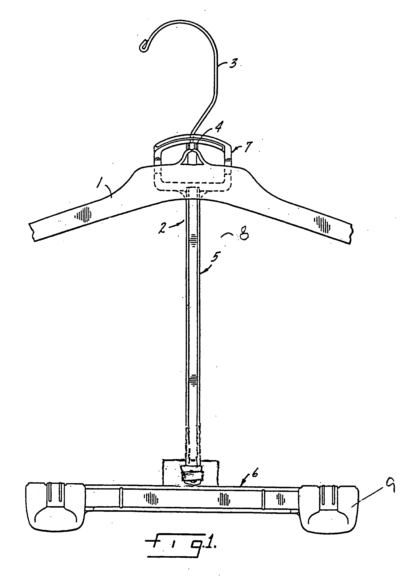
[0033]FIG. 1 depicts an embodiment of the present invention wherein the coordinate loop hanger 2 is suspended from the upper hanger 1. Upper hanger 1 exemplifies a particular style of upper garment hanger employing a metal hook 3, although other hanger styles, such as those having a plastic hook can be employed here as well. Coordinate loop hanger 2 includes ganging member 8 comprising loop 7 (shown here placed over hook 3 and resting on boss 4 of the upper hanger 1), an elongated member 5 attached to the loop 7. Hanger body 6 is provided with clamps 9 for retaining a garment within the jaws of the clamps. The clamps can be of any design known in this field of endeavor, and at least a portion of the clamps may be formed integral with the hanger body.

[0034] It should be observed that when the lower hanger 2 is suspended from the upper garment hanger 1, the upper garment hanger 1 can retain an upper body garment, such as a jacket, and the lower hanger 2 can retain a lower body garmen...


PUM


Abstract

The present invention is directed to the field of garment hangers, in particular, garment hangers for retaining and supporting lower body garments. Such hangers may be referred to as coordinate loop hangers, which coordinate loop hangers may be supported by upper garment hangers.

Description

CROSS-REFERENCE TO RELATED APPLICATIONS [0001] This application claims priority under 35 U.S.C. §119(e) of U.S. Provisional Patent Application Ser. No. 60 / 666,988, filed 31 Mar. 2005 (Attorney Docket 18616) by the present inventor and commonly assigned with the present application. The compete disclosure of the foregoing application is hereby incorporated by its reference for all purposes.FIELD OF THE INVENTION [0002] The present invention is directed to the field of garment hangers, in particular, garment hangers for retaining and supporting lower body garments. Such hangers may be referred to as coordinate loop hangers, which coordinate loop hangers may be supported by upper garment hangers. BACKGROUND OF THE INVENTION [0003] Many garments are designed for sale as matching outfits or sets. For example, a jacket and pant set, a jacket and top set, a short and top set, and other such combinations may be specifically manufactured to be sold as sets. In the sale of such garment sets, ...

Claims


Application Information

Patent Timeline
IPC IPC(8): A41D27/22
CPCA47G25/48A47G25/16A47F7/24A47G25/32A47G25/483
Inventor GOULDSON, STANLEY
Owner PROSPERITY PROD HK LTD
Why Eureka
Try Eureka