Radio communication system

a radio communication and radio chip technology, applied in the field of radio communication systems, can solve the problems of radio chips that are not capable of directly receiving radio waves from the transmitting/receiving device, and achieve the effect of high-reliability reading/writing communication

Inactive Publication Date: 2006-12-14
NEC CORP
View PDF5 Cites 234 Cited by
  • Summary
  • Abstract
  • Description
  • Claims
  • Application Information

AI Technical Summary

Benefits of technology

[0022] As described above, the present invention comprises the radio-wave directive unit in the space where a plurality of the radio IC chips are accumulated, and traveling direction of the radio waves from the transmitting/receiving device is directed towards the radio IC chips by the radio-wave directive unit. Thus

Problems solved by technology

Let us assume that there are radio chips that are not capable of directly receiving the radio

Method used


Image

  • Radio communication system
  • Radio communication system
  • Radio communication system

Examples


first embodiment

(First Embodiment)

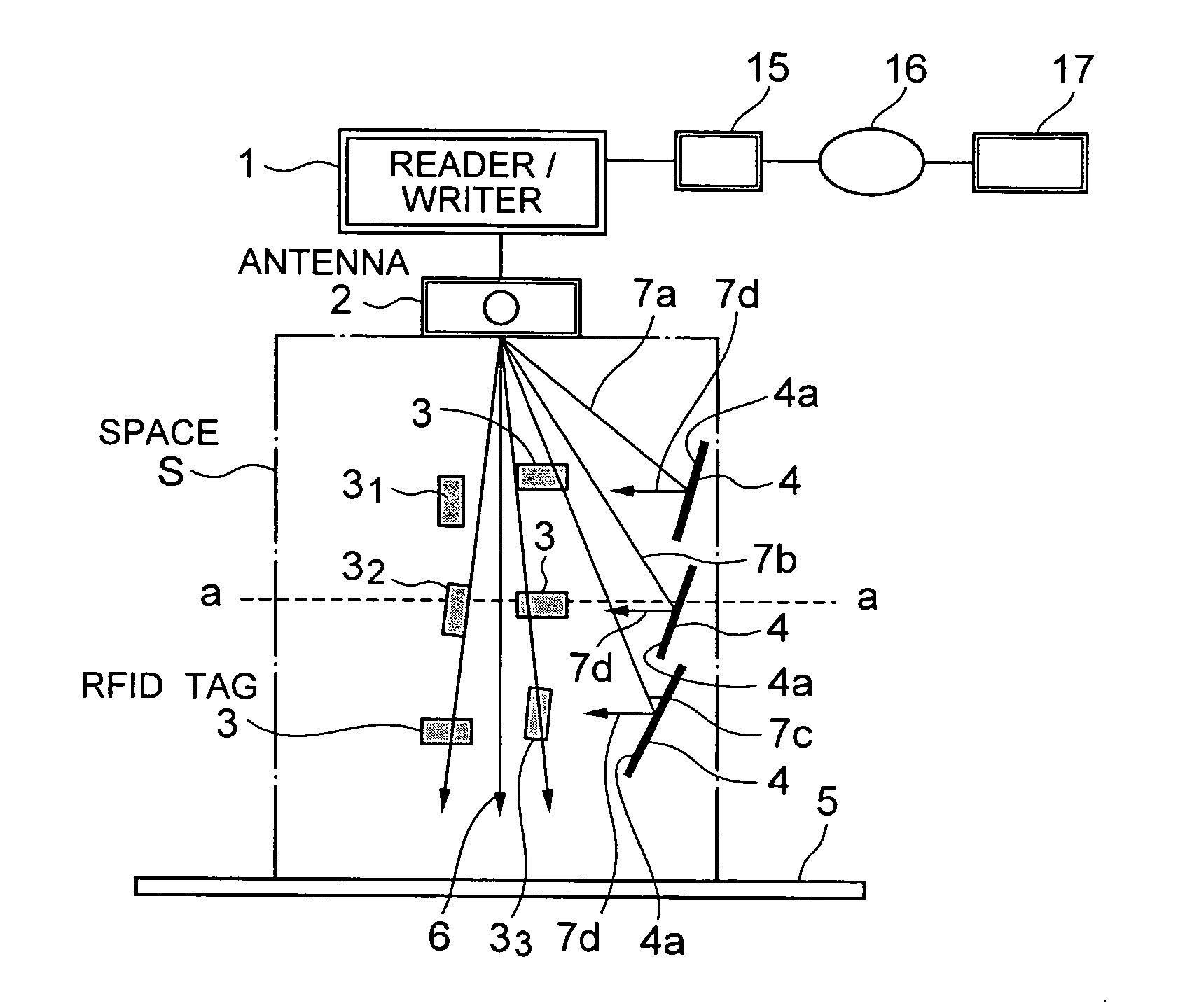
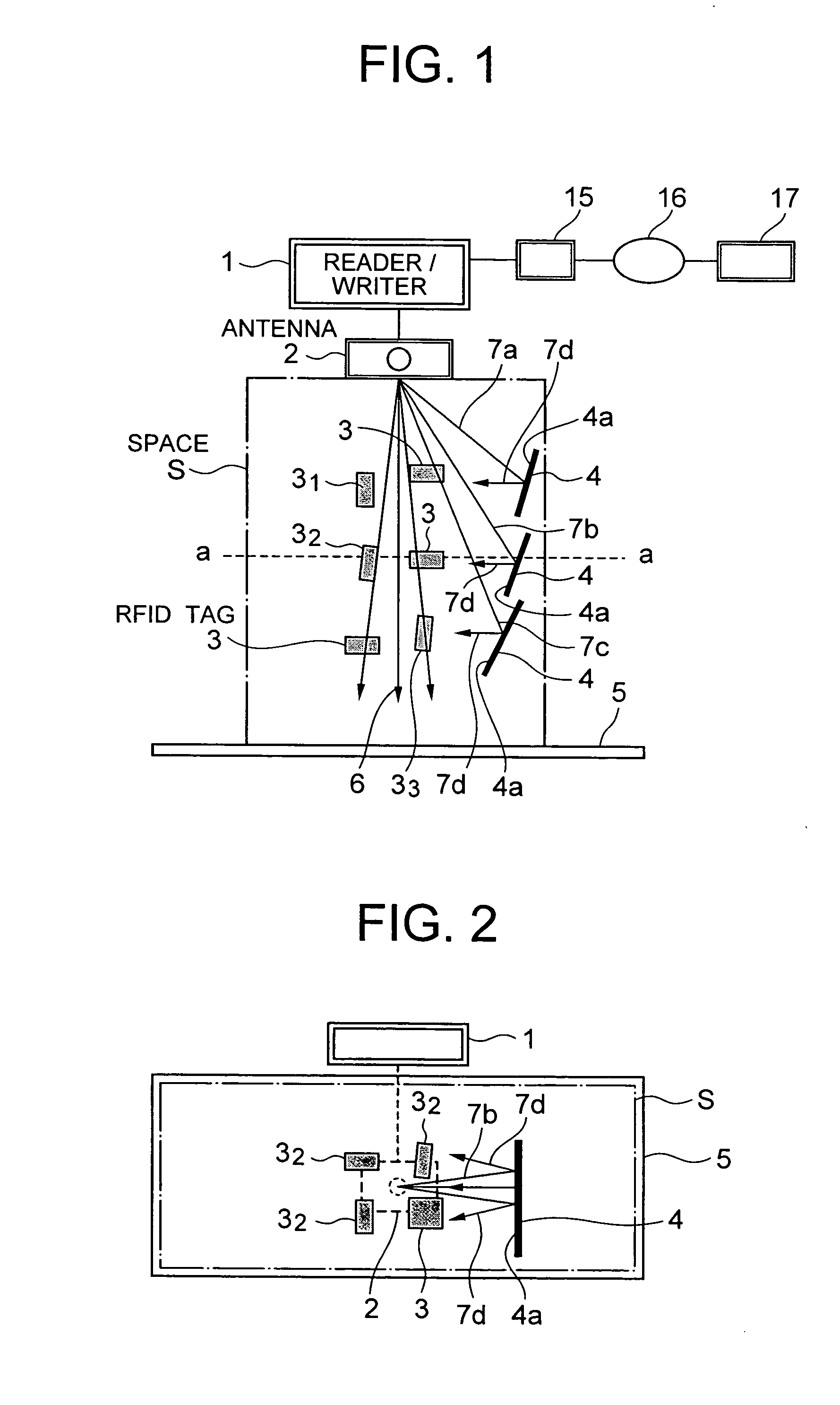
[0045]FIG. 1 and FIG. 2 show a first embodiment of the present invention. As shown in FIG. 1 and FIG. 2, commodities and the like to which the RFID tags 3 are attached are piled up vertically and collected at a depot. Other than the case of a store and a warehouse in the distribution process, the depot may be an aisle of the store or a carrier that passes through a production line. In short, the depot means the space S where a plurality of RFID tags 3 that are attached to the commodities and the like are accumulated. FIG. 1 illustrates only the RFID tags 3 attached to the commodities but the commodities themselves to which the RFID tags 3 are attached.

[0046] An antenna 2 of the reader / writer 1 is placed downwards at the upper position of the space S, e.g. at the ceiling of the warehouse, so that a traveling direction 6 of the radio waves is directed towards the space S for allowing the radio waves from the antenna 2 to cover most of the area within the space S. Ar...

second embodiment

(Second Embodiment)

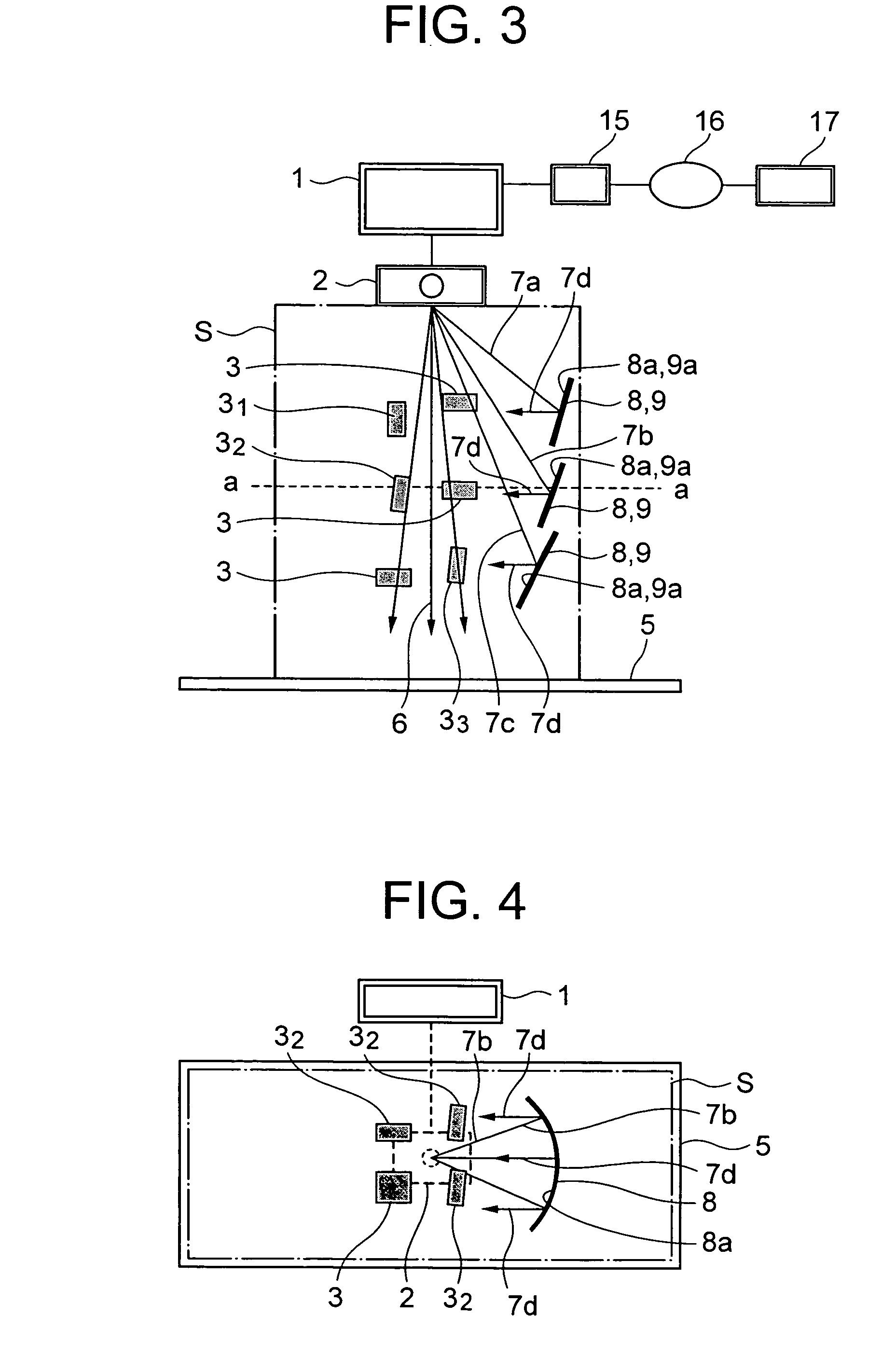
[0068]FIG. 3 and FIG. 4 show a second embodiment of the present invention. In the second embodiment of the present invention illustrated in FIG. 3 and FIG. 4, the reflecting surface 4a of the reflecting plate 4 shown in FIG. 1 is modified to a concave-shape reflecting surface.

[0069] A reflecting plate 8 according to the second embodiment of the present invention is formed in the following manner when viewed from the side-face side of the reflecting plate 8 while the reflecting plate 8 is being disposed as shown in FIG. 3. That is, a reflecting surface 8a along the traveling direction 6 of the radio waves from the antenna 2 of the reader / writer 1, i.e. the vertical direction (longitudinal direction) of the reflecting plate, is formed linearly (in a plane shape as a whole). Further, when viewed from the above in the state where the reflecting plate 8 is disposed as shown in FIG. 4, the cross section of the reflecting surface 8a of the reflecting plate 8 along the l...

third embodiment

(Third Embodiment)

[0073]FIG. 5 shows a third embodiment of the present invention. In the third embodiment of the present invention illustrated in FIG. 5, the reflecting surface 8a of the reflecting plate 8 shown in FIG. 2, which is in the secondary parabolic cylindrical surface, is modified to a cylindrical surface that is a kind of concave shapes.

[0074] As shown in FIG. 5, when a reflecting plate 9 according to the third embodiment of the present invention is viewed from the above while it is being placed, the cross section thereof along the length direction (lateral direction) is formed in a concave cylindrical face form. In this case, in the state where the reflecting plate 9 is disposed, the cross sectional shape of a reflecting surface 9a along the traveling direction 6 of the radio wave irradiated from the antenna 2 of the reader / writer 1, i.e. the vertical direction of the reflecting pate 9, is in a linear form (plane shape as a whole) as in the second embodiment. Further, t...


PUM


Abstract

It is to provide a radio communication system capable of performing highly reliable reading/writing communication even though the RFID tags face in the random directions. The radio communication system comprises an RFID tag used for identification, a reader/writer for performing transmission and reception of information between the RFID tag by radio waves, and a plurality of reflecting plates in a space where a plurality of RFID tags are accumulated. The reflecting plates direct traveling direction of the radio wave irradiated from the reader/writer towards the RFID tags. A part of the radio waves irradiated from an antenna of the reader/writer is directed to travel three-dimensionally towards the space by the effect of the reflecting plates. Moreover, the radio waves traveling in the same direction among the reflected radio waves by the plurality of reflecting plates together allow attenuation caused due to distance to be reduced extremely.

Description

BACKGROUND OF THE INVENTION [0001] 1. Field of the Invention [0002] The present invention relates to a radio communication system that is used in a distribution process of merchandise, for example, for managing the merchandise. [0003] 2. Description of the Related Art [0004] In stores such as supermarkets, commodities are arranged on display racks, and different kinds of commodities are stored in a warehouse of the store or in warehouses in the process of distribution. These commodities are not just stored but need to be supplied additionally when the current stocks are consumed. Further, the commodities need to be sent out according to orders. The radio communication system is used for managing those commodities. [0005] The radio communication system disclosed in Japanese Unexamined Patent Publication 2004-32067 utilizes an RFID technique, which is constituted with an RFID (Radio Frequency IDentification) tag comprising an antenna coil, a memory and the like, and a reader / writer mo...

Claims


Application Information

Patent Timeline
IPC IPC(8): G06K7/08G06K7/00
CPCG06K7/10178G06K7/0008G06F16/24
Inventor HATAKEYAMA, SHIGERUYAMAYAKI, SHIGERUMURAYAMA, HIROKIHIRANO, KOUICHI
Owner NEC CORP
Why Eureka
Try Eureka