Radio communication system
a radio communication and radio chip technology, applied in the field of radio communication systems, can solve the problems of radio chips that are not capable of directly receiving radio waves from the transmitting/receiving device, and achieve the effect of high-reliability reading/writing communication
- Summary
- Abstract
- Description
- Claims
- Application Information
AI Technical Summary
Benefits of technology
Problems solved by technology
Method used
Image
Examples
first embodiment
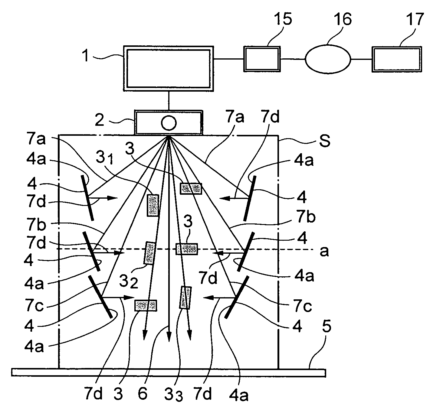
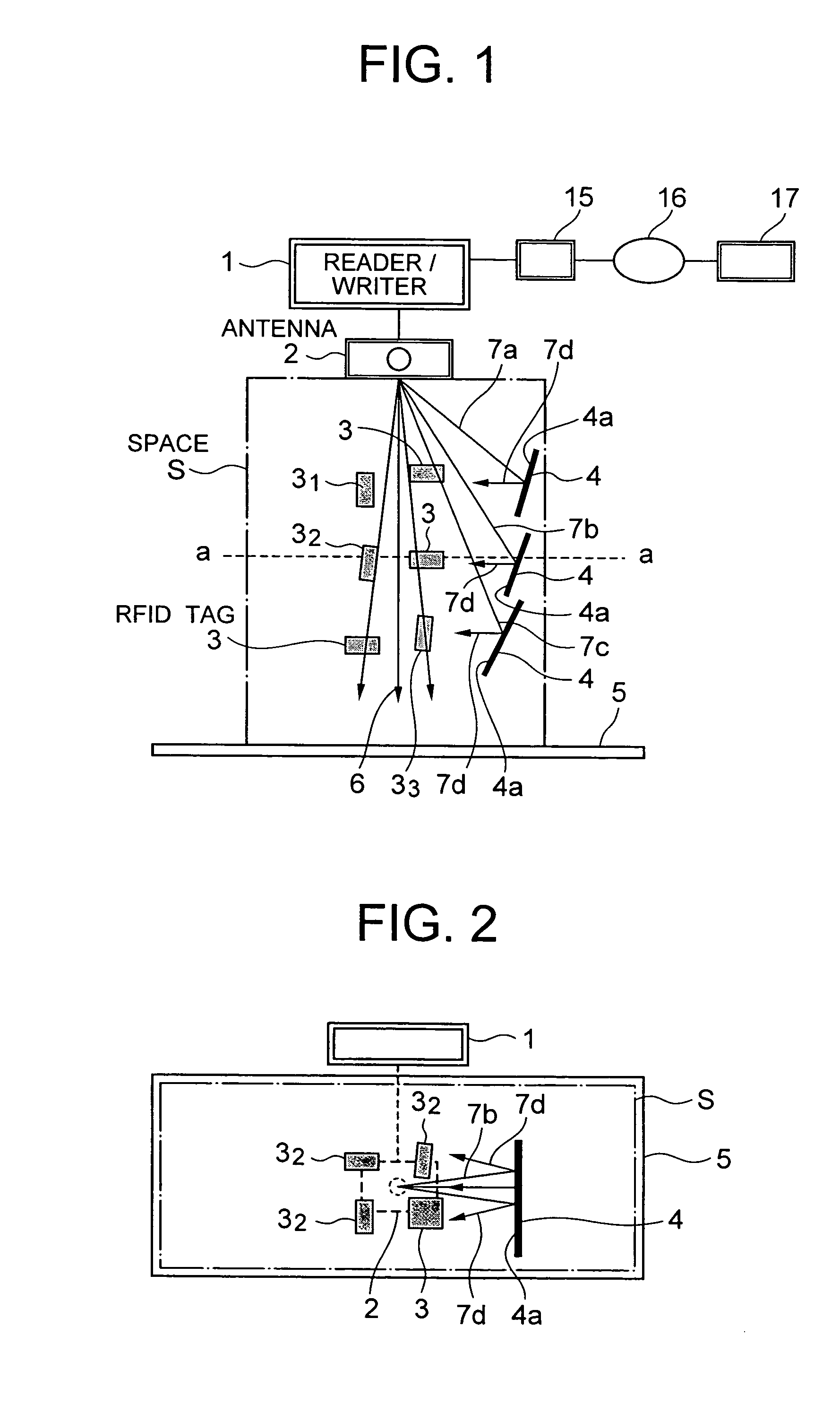
[0045]FIG. 1 and FIG. 2 show a first embodiment of the present invention. As shown in FIG. 1 and FIG. 2, commodities and the like to which the RFID tags 3 are attached are piled up vertically and collected at a depot. Other than the case of a store and a warehouse in the distribution process, the depot may be an aisle of the store or a carrier that passes through a production line. In short, the depot means the space S where a plurality of RFID tags 3 that are attached to the commodities and the like are accumulated. FIG. 1 illustrates only the RFID tags 3 attached to the commodities but the commodities themselves to which the RFID tags 3 are attached.
[0046]An antenna 2 of the reader / writer 1 is placed downwards at the upper position of the space S, e.g. at the ceiling of the warehouse, so that a traveling direction 6 of the radio waves is directed towards the space S for allowing the radio waves from the antenna 2 to cover most of the area within the space S. Arrows extended from t...
second embodiment
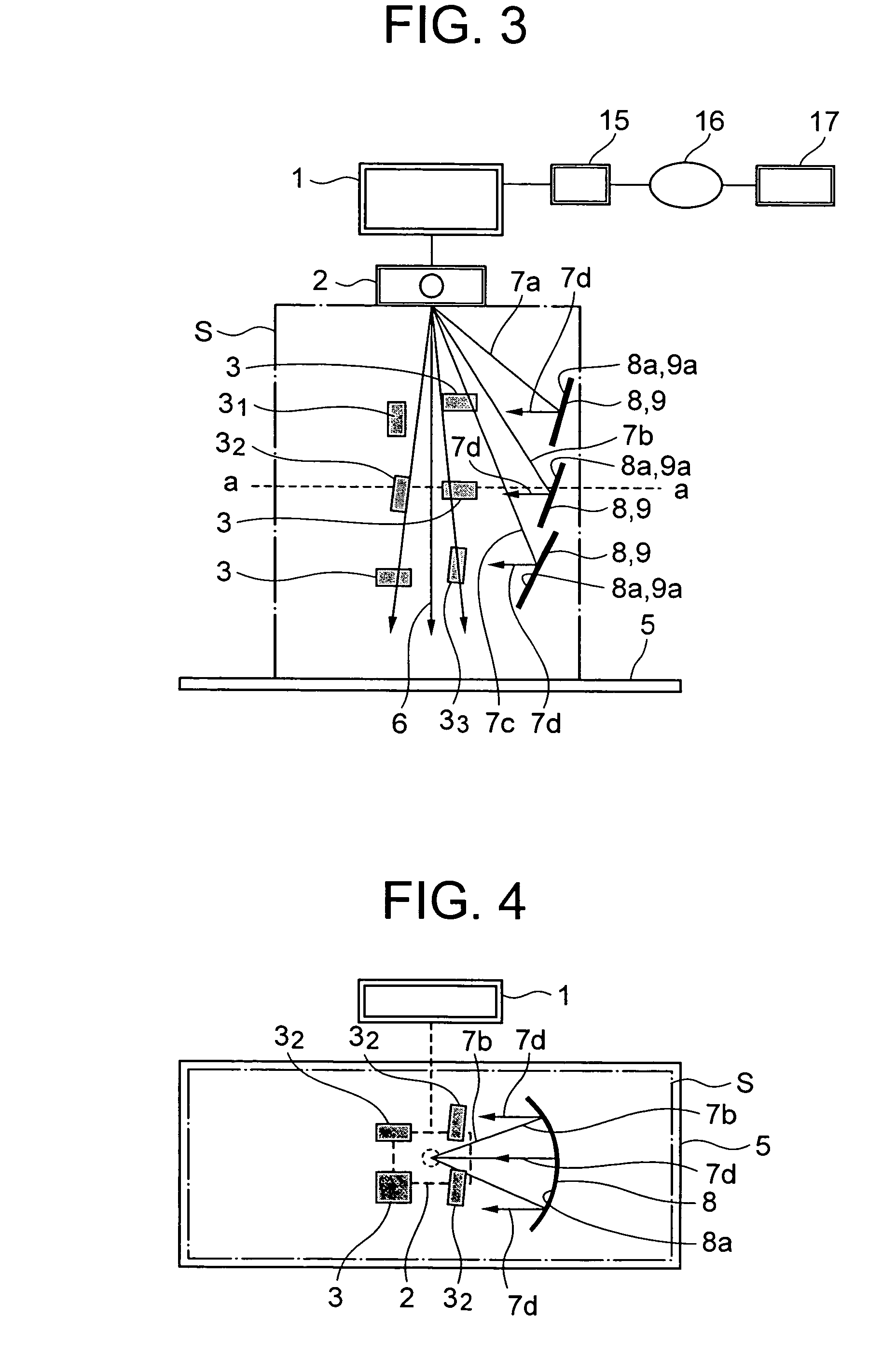
[0068]FIG. 3 and FIG. 4 show a second embodiment of the present invention. In the second embodiment of the present invention illustrated in FIG. 3 and FIG. 4, the reflecting surface 4a of the reflecting plate 4 shown in FIG. 1 is modified to a concave-shape reflecting surface.
[0069]A reflecting plate 8 according to the second embodiment of the present invention is formed in the following manner when viewed from the side-face side of the reflecting plate 8 while the reflecting plate 8 is being disposed as shown in FIG. 3. That is, a reflecting surface 8a along the traveling direction 6 of the radio waves from the antenna 2 of the reader / writer 1, i.e. the vertical direction (longitudinal direction) of the reflecting plate, is formed linearly (in a plane shape as a whole). Further, when viewed from the above in the state where the reflecting plate 8 is disposed as shown in FIG. 4, the cross section of the reflecting surface 8a of the reflecting plate 8 along the length direction (late...
third embodiment
[0073]FIG. 5 shows a third embodiment of the present invention. In the third embodiment of the present invention illustrated in FIG. 5, the reflecting surface 8a of the reflecting plate 8 shown in FIG. 2, which is in the secondary parabolic cylindrical surface, is modified to a cylindrical surface that is a kind of concave shapes.
[0074]As shown in FIG. 5, when a reflecting plate 9 according to the third embodiment of the present invention is viewed from the above while it is being placed, the cross section thereof along the length direction (lateral direction) is formed in a concave cylindrical face form. In this case, in the state where the reflecting plate 9 is disposed, the cross sectional shape of a reflecting surface 9a along the traveling direction 6 of the radio wave irradiated from the antenna 2 of the reader / writer 1, i.e. the vertical direction of the reflecting pate 9, is in a linear form (plane shape as a whole) as in the second embodiment. Further, the reflecting plate ...
PUM
 Abstract
Description
Claims
Application Information
 - R&D
- Intellectual Property
- Life Sciences
- Materials
- Tech Scout
- Unparalleled Data Quality
- Higher Quality Content
- 60% Fewer Hallucinations
Browse by: Latest US Patents, China's latest patents, Technical Efficacy Thesaurus, Application Domain, Technology Topic, Popular Technical Reports.
© 2025 PatSnap. All rights reserved.Legal|Privacy policy|Modern Slavery Act Transparency Statement|Sitemap|About US| Contact US: help@patsnap.com


