Intelligent optical systems and methods for optical-layer management

a technology of intelligent optical systems and optical layers, applied in electromagnetic transceivers, transmission monitoring/testing/fault-measurement systems, transmission monitoring, etc., to achieve the effect of facilitating communication, and reducing the need for demarcation equipmen

Active Publication Date: 2011-04-26
BROADWAY NETWORKS +1
View PDF19 Cites 45 Cited by
  • Summary
  • Abstract
  • Description
  • Claims
  • Application Information

AI Technical Summary

Benefits of technology

Embodiments may include one or more of the following advantages. The disclosed systems and methods provide more reliable communications by direct and reliable monitoring of optical communications by establishing an optical layer communication channel that is non-intrusive to the user data traffic. The disclosed systems and methods can eliminate the needs for demarcation equipment in some conventional optical network systems. The functions of the optical transceivers are enriched by functions integrated in an optical transceiver, which include non-intrusive optical communication channel, optical layer management, and data feedback capability. These functions are not available in the conventional optical transceivers.
Moreover, optical layer management is provided without adding overhead to the user data and the host equipment into which the disclosed optical transceivers are plugged. The disclosed system and methods do not require costly installations (such as digital wrapper or extra interoperable equipment) at customer premises. Furthermore, the disclosed optical transceiver is compliant with industry-standard optical transceiver formats. The disclosed optical transceiver can be implemented as a device which receives electric power from the host equipment into which it is plugged. The disclosed optical transceiver is applicable to a multi-channel optical communication network such as an optical network between an optical terminal, remote nodes, and optical network units.
Furthermore, the disclosed systems and methods provide optical loop back that allows remote testing of optical links in addition to data loop-back function or when data loop-back function is unavailable. The optical loop back can be implemented in optical transceiver devices and can function during power failures. “Dying gasp” monitoring, reporting, and detection are provided by optical-layer communication, which can be faster in response.

Problems solved by technology

As service provides' networks are becoming more complex, reliable services and effective management of the networks have become key challenges for service providers to ensure service level agreement (SLA) and guarantee customer satisfaction.

Method used


Image

  • Intelligent optical systems and methods for optical-layer management
  • Intelligent optical systems and methods for optical-layer management
  • Intelligent optical systems and methods for optical-layer management

Examples


Embodiment Construction

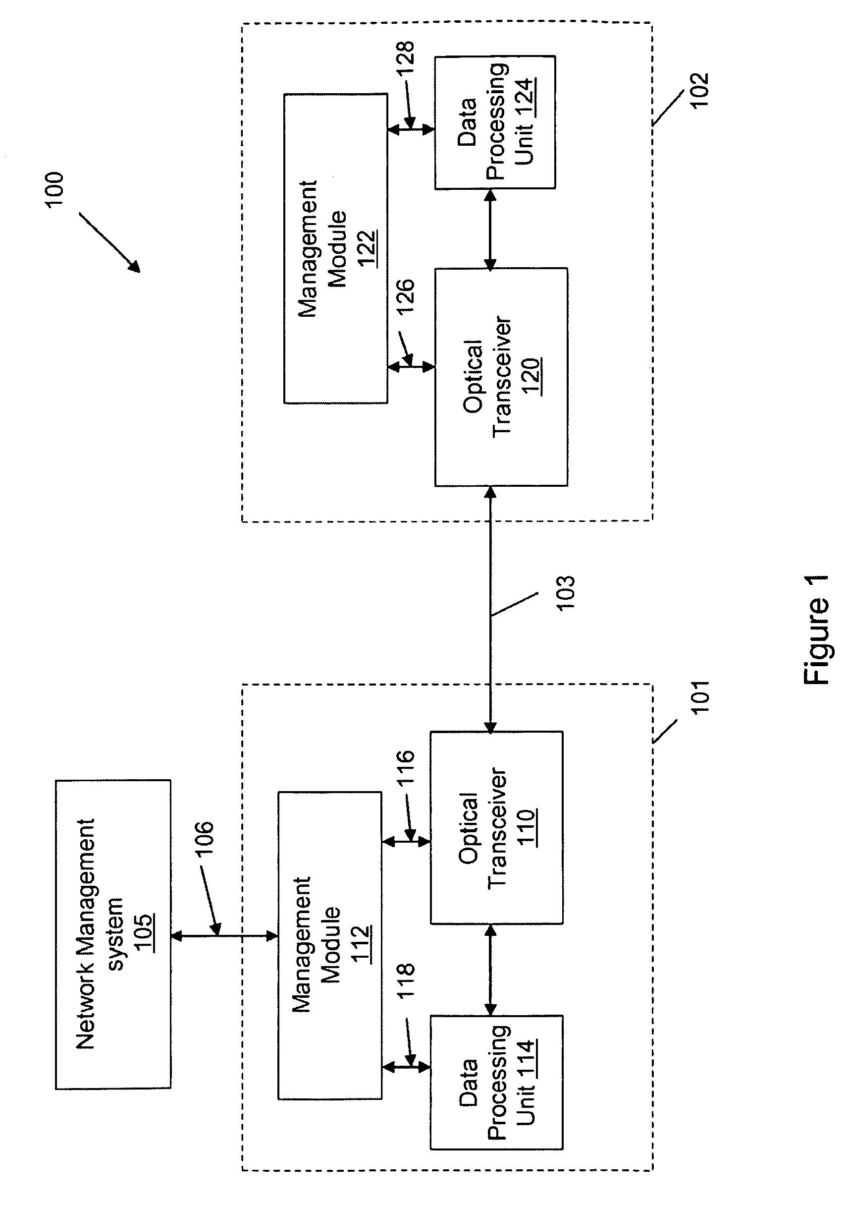
Referring to FIG. 1, an optical network system 100 includes network equipment 101 and 102 that are installed at different locations and can communicate in optical signals via an optical link 103. The optical link 103 can for example include a single optical fiber, or a cable containing a bundle of optical fiber. The equipment 101 includes an optical transceiver 110 that is configured to perform conversions between optical and electrical signals, a data processing unit 114 that processes communication signals, and a management module 112 that monitors and controls the functions of the network equipment 101. Similarly, the equipment 102 includes an optical transceiver 120 capable of performing conversions between optical and electrical signals, a data processing unit 124 that processes the communication signals, and a management module 122 that monitors and controls the functions of the network equipment 102. Optionally, a higher level network management system 105 manages entire netw...


PUM


Abstract

An integrated optical transceiver includes an optical receiver that produces a first electrical signal at a reception electrical interface in response to a first optical signal, an optical transmitter that emits a second optical signal in response to a second electrical signal received at a transmission electrical interface, a first optical branching device that receives the first optical signal at an reception optical interface and to direct at least a portion of the first optical signal to the optical receiver, and a second optical branching device that directs the second optical signal to an transmission optical interface. The first optical branching device directs at least a portion of the first optical signal to the second optical branching device. The second optical branching device directs the portion of the first optical signal received from the first optical branching device to the transmission optical interface.

Description

BACKGROUNDThe present disclosure relates to optical networking systems and optical transceivers used in the systems.As voice over Internet Protocol (VoIP) and Internet Protocol television (IPTV) grow in popularity, an increasing number of users desire to have access to these services from their premises. Similarly, businesses now require more bandwidth available to their premises with necessary quality of service. To meet these needs, network carriers are building optical access networks with different network topologies such as fiber-to-the-premises, fiber-to-the-node, or fiber-to-the-building with many different access transport solutions including BPON, EPON, GPON, WDN-PON and active Ethernet. As service provides' networks are becoming more complex, reliable services and effective management of the networks have become key challenges for service providers to ensure service level agreement (SLA) and guarantee customer satisfaction.SUMMARYIn a general aspect, the present specificat...

Claims


Application Information

Patent Timeline
Patent Type & Authority Patents(United States)
IPC IPC(8): H04B10/08
CPCH04B10/40
Inventor LI, WENZHOU, JIANHUIHUANG, WENPAN, FULIN
Owner BROADWAY NETWORKS
Why Eureka
Try Eureka