
Laminated contact lens

a contact lens and laminate technology, applied in the field of contact lenses, can solve the problems of limiting the utility of the contact lens and the cost of making contact lenses for different functions,

Inactive Publication Date: 2006-12-28
PARAGON VISION SCI INC
View PDF6 Cites 155 Cited by
  • Summary
  • Abstract
  • Description
  • Claims
  • Application Information

AI Technical Summary

Benefits of technology

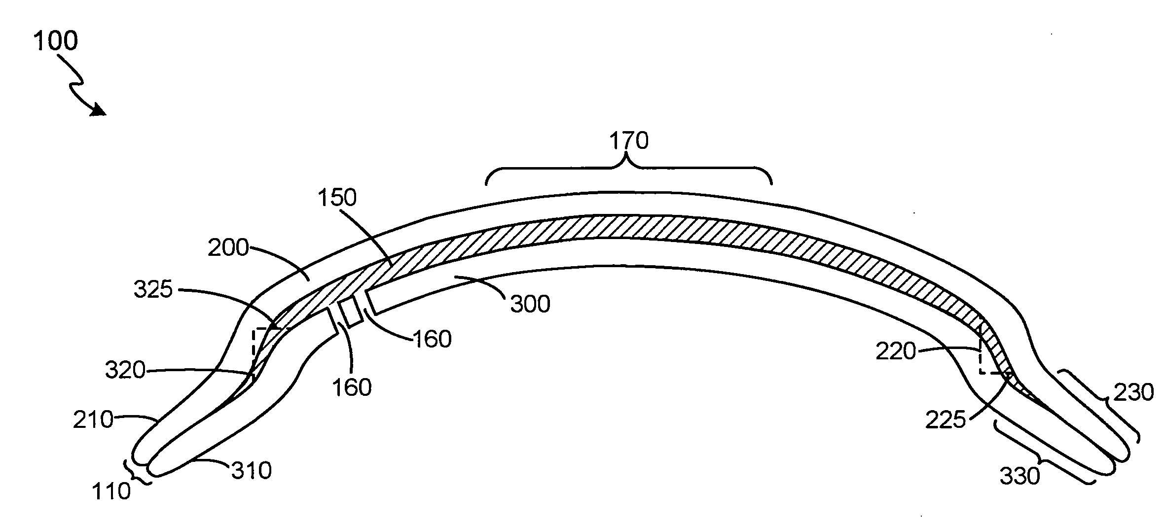
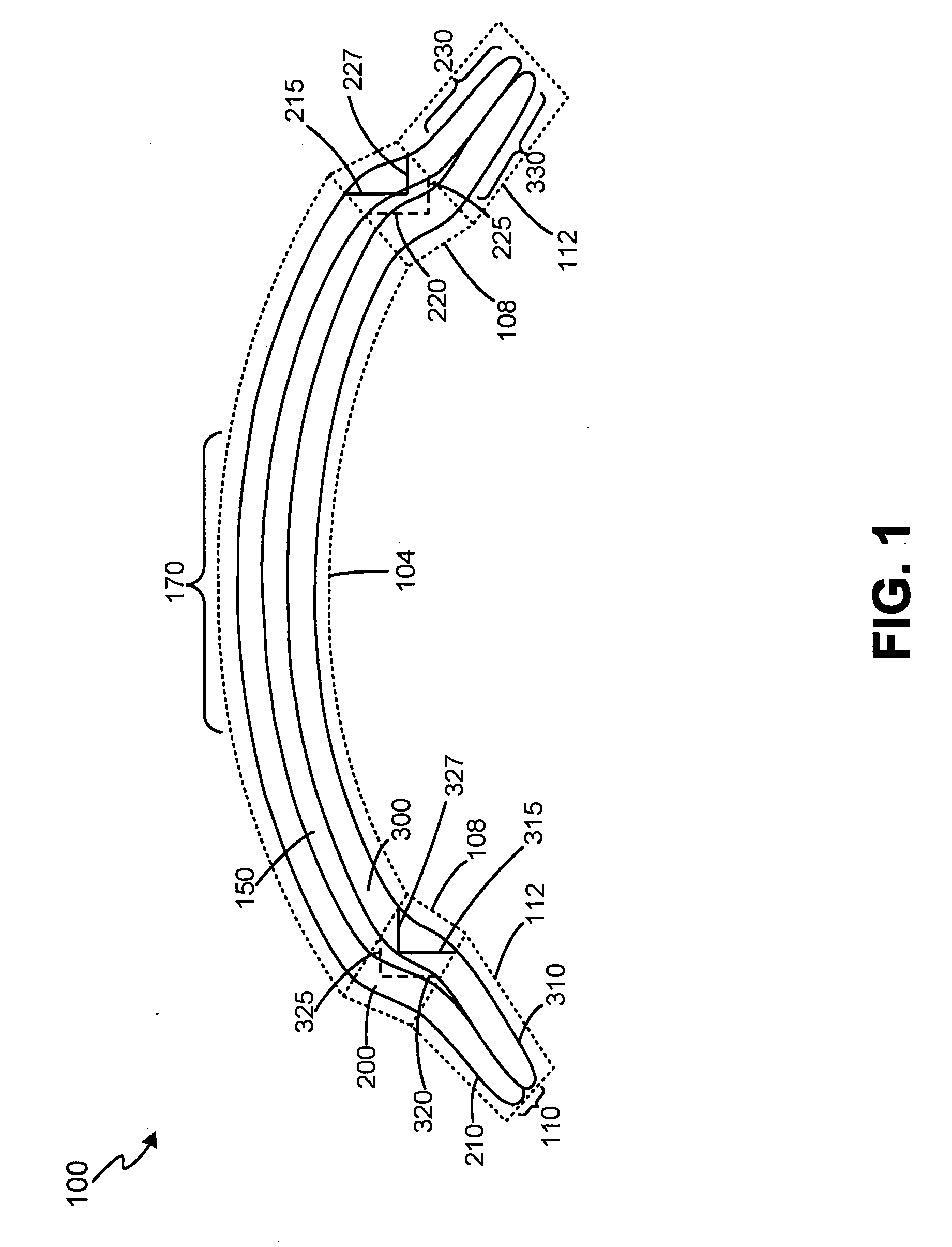
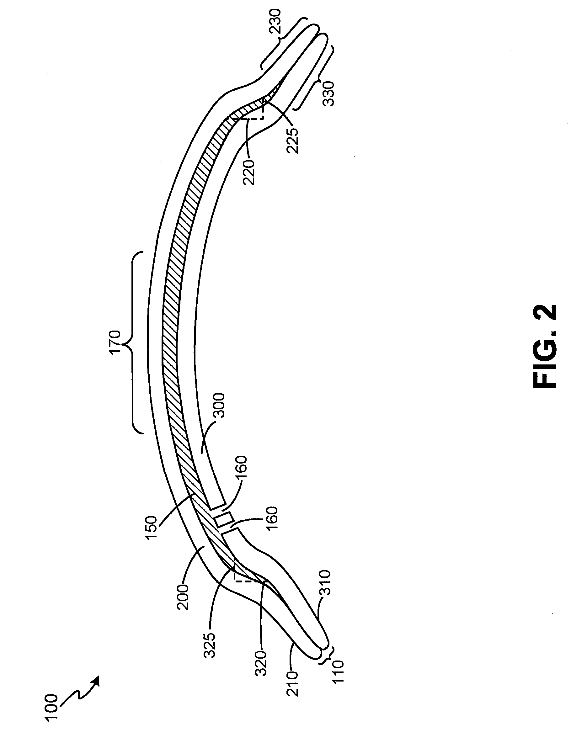
[0010] In an exemplary embodiment, the difference between the first variable PZD and the second variable PZD, and / or the first variable PZW and the second variable PZW creates one or more chambers between the first contact lens and the second contact lens. The volume of each chamber is capable of being manipulated by the size of the contact lens, the absolute and relative widths and / or radial locations of the corresponding zones of the anterior and posterior lenses, the difference between the first variable PZD and the second variable PZD, and / or the difference between the first variable PZW and the second variable PZW of the first contact lens and the second contact lens, respectively. The formation of the chamber enables different materials and / or components having functions differing from one other to be housed by the chamber. As such, by changing / interchanging the different materials and / or components that are housed by the chamber, the function(s) of the contact lens may be changed.

Problems solved by technology

While different uses for contact lenses exist, the fact that typical contact lenses include a single continuous layer limits the utility of the contact lens.
As such, the cost of making contact lenses for different functions is often costly.

Method used


Image

  • Laminated contact lens
  • Laminated contact lens
  • Laminated contact lens

Examples


Embodiment Construction

[0019] The detailed description of exemplary embodiments of the invention herein makes reference to the accompanying Figures, which show the exemplary embodiment by way of illustration and its best mode. While these exemplary embodiments are described in sufficient detail to enable those skilled in the art to practice the invention, it should be understood that other embodiments may be realized and that logical and mechanical changes may be made without departing from the spirit and scope of the invention. Thus, the detailed description herein is presented for purposes of illustration only and not of limitation.

[0020] For the sake of brevity, functional embodiments of the apparatus and systems (and components of the individual operating components of the systems) may not be described in detail herein. Furthermore, the connecting lines shown in the various figures contained herein are intended to represent exemplary functional relationships and / or physical connection between the var...


PUM


Abstract

A laminated contact lens according to the present invention includes at least a first contact lens and a second contact lens coupled to each other via the peripheral edge of each respective contact lens. The two contact lenses include a proximity zone depth and / or proximity zone width different from one another such that one or more chambers are formed between the two contact lenses. Various materials and / or components may be housed within the chamber to provide, among other things, vision correction tools, medicament administration, and / or cosmetic improvements to the user.

Description

CROSS-REFERENCE TO RELATED APPLICATIONS [0001] This application claims priority to, and the benefit of, U.S. Provisional Application Ser. No. 60 / 595,370 entitled “Laminated Contact Lens,” filed on Jun. 27, 2005, and hereby incorporates such provisional application by reference, in its entirety.FIELD OF INVENTION [0002] The invention generally relates to contact lenses, and particularly to, a laminated contact lens having one or more chambers formed between two or more contact lens layers. BACKGROUND OF THE INVENTION [0003] Contact lenses have existed since the time of Leonardo Da Vinci. Historically, contact lenses have been used to correct the vision of the user. In the early to mid twentieth century, contact lenses were beginning to be formed of plastic materials rather than glass. In the mid to late twentieth century, contact lens began to be formed of more flexible plastic materials. [0004] Typical contact lenses include a circular or elliptical shape formed of a single contact ...

Claims


Application Information

Patent Timeline
IPC IPC(8): G02C7/04A61K9/00
CPCG02C7/047G02C7/049G02C7/021G02C2202/16G02C7/104
Inventor MEYERS, WILLIAM E.STUTE, HANK L.
Owner PARAGON VISION SCI INC
Learn More