Control apparatus for internal combustion engine

a control apparatus and internal combustion engine technology, applied in the direction of electrical control, process and machine control, instruments, etc., can solve the problem of unlikely deposits, and achieve the effect of suppressing deposits and maintaining stable combustion

Inactive Publication Date: 2007-01-04
TOYOTA JIDOSHA KK
View PDF9 Cites 45 Cited by
  • Summary
  • Abstract
  • Description
  • Claims
  • Application Information

AI Technical Summary

Benefits of technology

[0017] In view of the foregoing, an object of the present invention is to provide a control apparatus for an internal combustion engine that obviates generation of an operation noise from a high-pressure fuel pump, maintains stable combustion, and suppresses generation of deposits at the injection hole of a fuel injection mechanism during an idling mode of the internal combustion engine.
[0019] In accordance with the present invention, determination is made that the operation state of the internal combustion engine is in an idle state based on, for example, the engine speed and the load state of the internal combustion engine. With regards to the idle state, it is predetermined which of two or more idle states the idle state belongs to according to the temperature of the internal combustion engine. The internal combustion engine is under control depending upon which of the idle states the current idle state belongs to. Specifically, in a cold idle state among the idle states, deposits are unlikely to be generated at the injection hole of the first fuel injection mechanism since the temperature is low. Therefore, combustion stability is given priority than obviating generation of deposits. The high-pressure pump is stopped and low-pressure fuel is injected from the second fuel injection mechanism alone. Thus, a favorable combustion state can be realized even when the temperature is low. In a warm idle state, the problem of combustion stability is less likely to occur since the temperature is not low. Therefore, avoiding generation of deposits is given priority than combustion stability. The high-pressure pump is stopped and low-pressure fuel is injected from the first fuel injection mechanism and / or the second fuel injection mechanism. The operation noise can be reduced since the high-pressure pump is stopped. Since fuel is injected from the second fuel injection mechanism when in a cold idle state, the time from fuel injection up to ignition is increased to improve atomization, whereby combustion can be stabilized. Further, since high-pressure fuel is injected from the first fuel injection mechanism when in a high temperature idle state, the temperature at the injection hole is reduced to obviate generation of deposits. Thus, there can be provided a control apparatus for an internal combustion engine that obviates generation of an operation noise of a high pressure pump, maintains stable combustion, and suppresses generation of deposits at the injection hole of the fuel injection mechanism when in an idling mode of the internal combustion engine.
[0021] In accordance with the present invention, control is effected such that the high-pressure pump is stopped or such that the discharge pressure from the high-pressure pump is reduced when in a cold idle state. Therefore, generation of the operation noise of the high-pressure pump when the internal combustion engine is in an idling mode can be obviated. Further, since fuel is injected from the second fuel injection mechanism in a cold idle state, the time from fuel combustion up to ignition is increased to improve atomization. Thus, combustion can be stabilized.
[0025] The possibility of deposits being generated at the injection hole of the first fuel injection mechanism is increased as the temperature of the internal combustion engine becomes higher, leading to unstable combustion. In accordance with the present invention, control is effected such that more fuel is injected from the first fuel injection mechanism as the temperature of the internal combustion engine becomes higher. Thus, generation of deposits can be obviated.
[0031] Similarly to the above-described invention, there can be provided a control apparatus for an internal combustion engine that obviates generation of an operation noise of the high-pressure pump, maintains stable combustion, and suppresses generation of deposits at the injection hole of the fuel injection mechanism when in an idling mode of the internal combustion engine.
[0033] In accordance with the present invention, there can be provided a control apparatus for an internal combustion engine that has an in-cylinder injector and an intake manifold injector qualified as the first fuel injection mechanism and the second fuel injection mechanism, respectively, provided independently, for partaking in fuel injection to obviate generation of an operation noise of the high-pressure fuel pump, maintain stable combustion, and suppress generation of deposits at the injection hole of the fuel injection mechanism in an idling mode of the internal combustion engine.

Problems solved by technology

Specifically, in a cold idle state among the idle states, deposits are unlikely to be generated at the injection hole of the first fuel injection mechanism since the temperature is low.

Method used


Image

  • Control apparatus for internal combustion engine
  • Control apparatus for internal combustion engine
  • Control apparatus for internal combustion engine

Examples


first embodiment

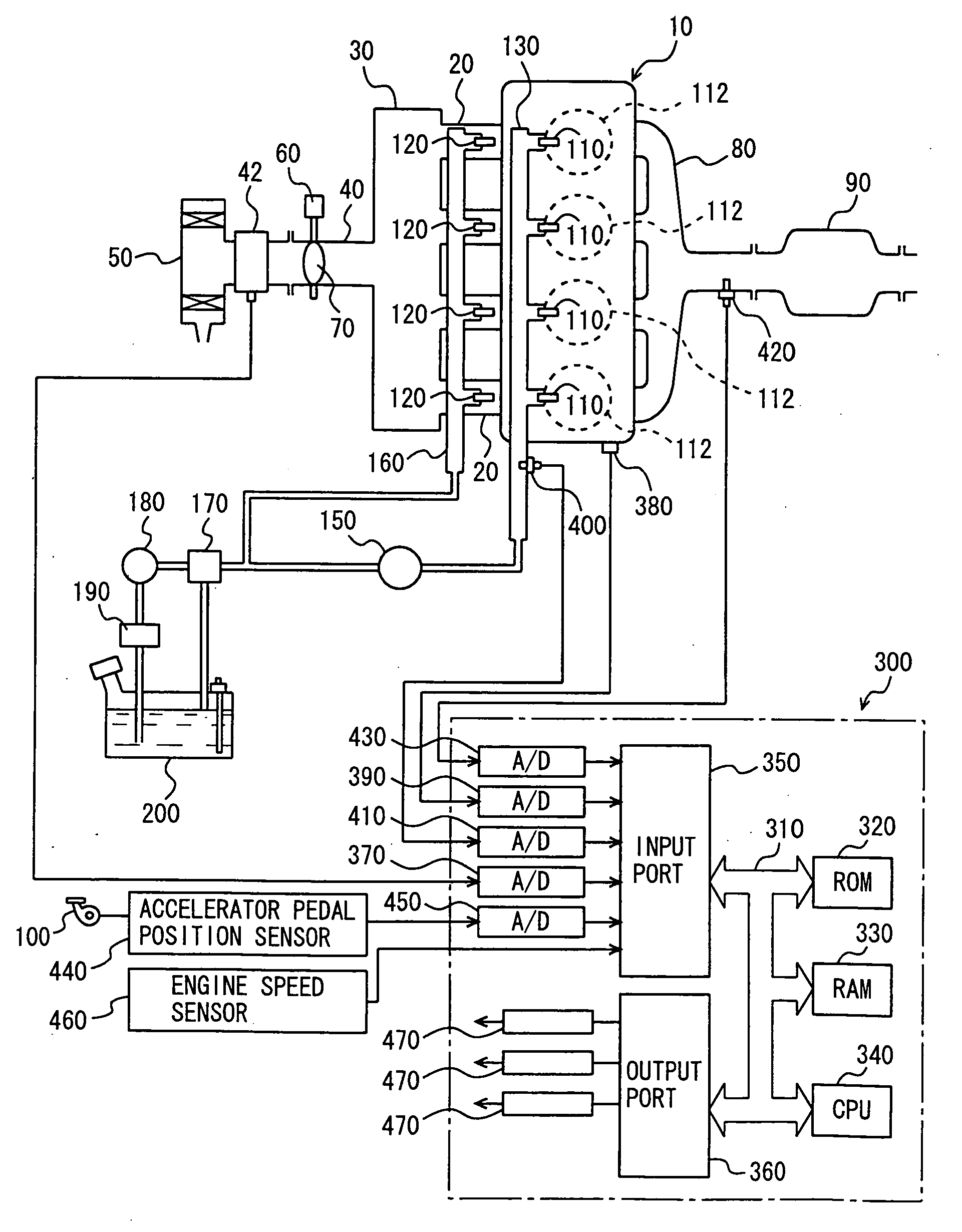
[0046]FIG. 1 schematically shows a configuration of an engine system under control of an engine ECU (Electronic Control Unit) qualified as a control apparatus for an internal combustion engine according to a first embodiment of the present invention. Although an in-line 4-cylinder gasoline engine is shown in FIG. 1, application of the present invention is not limited to the engine shown, and a V-type 6-cylinder engine, a V-type 8-cylinder engine, an in-line 6-cylinder engine, and the like may be employed. The present invention is applicable as long as the engine includes an in-cylinder injector for each cylinder.

[0047] Referring to FIG. 1, an engine 10 includes four cylinders 112, which are all connected to a common surge tank 30 via intake manifolds 20, each corresponding to a cylinder 112. Surge tank 30 is connected to an air cleaner 50 via an intake duct 40. An air flow meter 42 is arranged together with a throttle valve 70 driven by an electric motor 60 in intake duct 40. Throt...

second embodiment

[0101] An engine system under control of an engine ECU 300 qualified as a control apparatus for an internal combustion engine according to a second embodiment of the present invention will be described hereinafter. Engine ECU 300 of the second embodiment executes a program that differs partially from the program of the above-described first embodiment. The remaining hardware configuration (FIGS. 1-8) is similar to that of the first embodiment. Therefore, details thereof will not be repeated here.

[0102] Engine ECU 300 of the second embodiment executes effective control when switched from the state of high-pressure fuel pump 1200 being operated to supply high-pressure fuel from in-cylinder injector 110 to the state of injecting fuel of low pressure from in-cylinder injector 110 in a transitional idle region or warm idle region.

[0103] A control program executed by engine ECU 300 of the second embodiment will be described hereinafter with reference to the flow chart of FIG. 10. In the...


PUM


Abstract

An engine ECU executes a program including the steps of: detecting an engine speed NE, engine load, and engine coolant temperature (S100, S110, S115); when determination is made of being in an idle region (YES at S120), determining whether in a cold idle region, a transitional region, or a warm idle region (S130); injecting fuel from an intake manifold injector alone when in the cold idle region (S140); injecting fuel from the intake manifold injector and injecting fuel from an in-cylinder injector at the feed pressure when in the transitional region (S150); and injecting fuel from the in-cylinder injector at the feed pressure when in the warm idle region (S160).

Description

[0001] This nonprovisional application is based on Japanese Patent Application No. 2005-192047 filed with the Japan Patent Office on Jun. 30, 2005, the entire contents of which are hereby incorporated by reference. BACKGROUND OF THE INVENTION [0002] 1. Field of the Invention [0003] The present invention relates to a control apparatus for an internal combustion engine including a fuel injection mechanism (in-cylinder injector) injecting fuel at high pressure into a cylinder, or an internal combustion engine including, in addition to the aforementioned fuel injection mechanism, another type of a fuel injection mechanism (intake manifold injector) injecting fuel towards an intake manifold or intake port. Particularly, the present invention relates to control of an internal combustion engine in an idling mode. [0004] 2. Description of the Background Art [0005] There is known an engine including a first fuel injection valve (in-cylinder injector) for injecting fuel into the combustion ch...

Claims


Application Information

Patent Timeline
Patent Type & Authority Applications(United States)
IPC IPC(8): F02B7/00F02M57/02
CPCF02D41/08F02M69/046F02M63/029F02D41/38F02D41/086F02D41/3094F02D2200/021
Inventor SADAKANE, SHINJIOHTANI, MOTOKIFUJIOKA, KAZUTAKA
Owner TOYOTA JIDOSHA KK
Why Eureka
Try Eureka