Walking aid

Inactive Publication Date: 2007-01-04
RUSSO PAUL C
View PDF24 Cites 45 Cited by
  • Summary
  • Abstract
  • Description
  • Claims
  • Application Information

AI Technical Summary

Benefits of technology

[0005] In accordance with another aspect of the present invention, a walking aid comprises a vertical shaft, a handle disposed at a top end of the shaft, an electrical component on the walking aid, and at least one

Problems solved by technology

Typical walking aids reflect a general lack of consideration to various design features of walking aids, such as how lights should

Method used


Image

  • Walking aid
  • Walking aid
  • Walking aid

Examples


Embodiment Construction

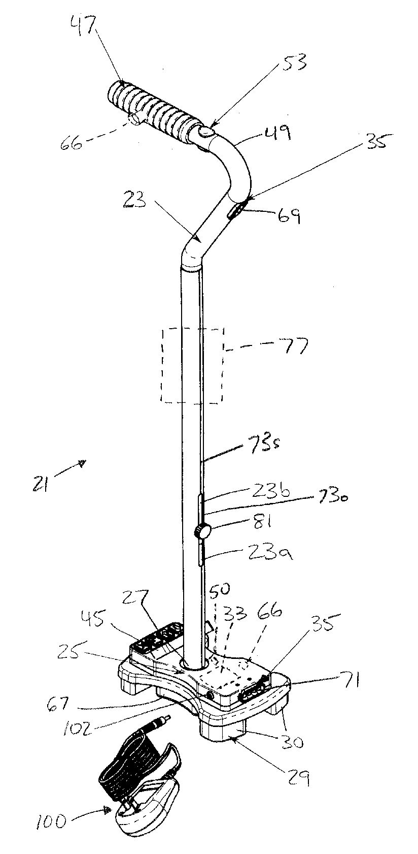
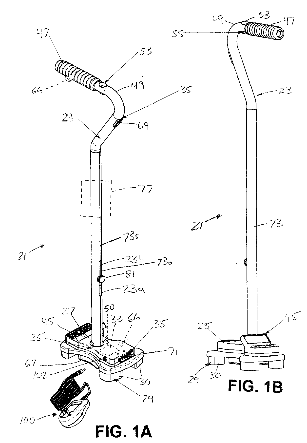
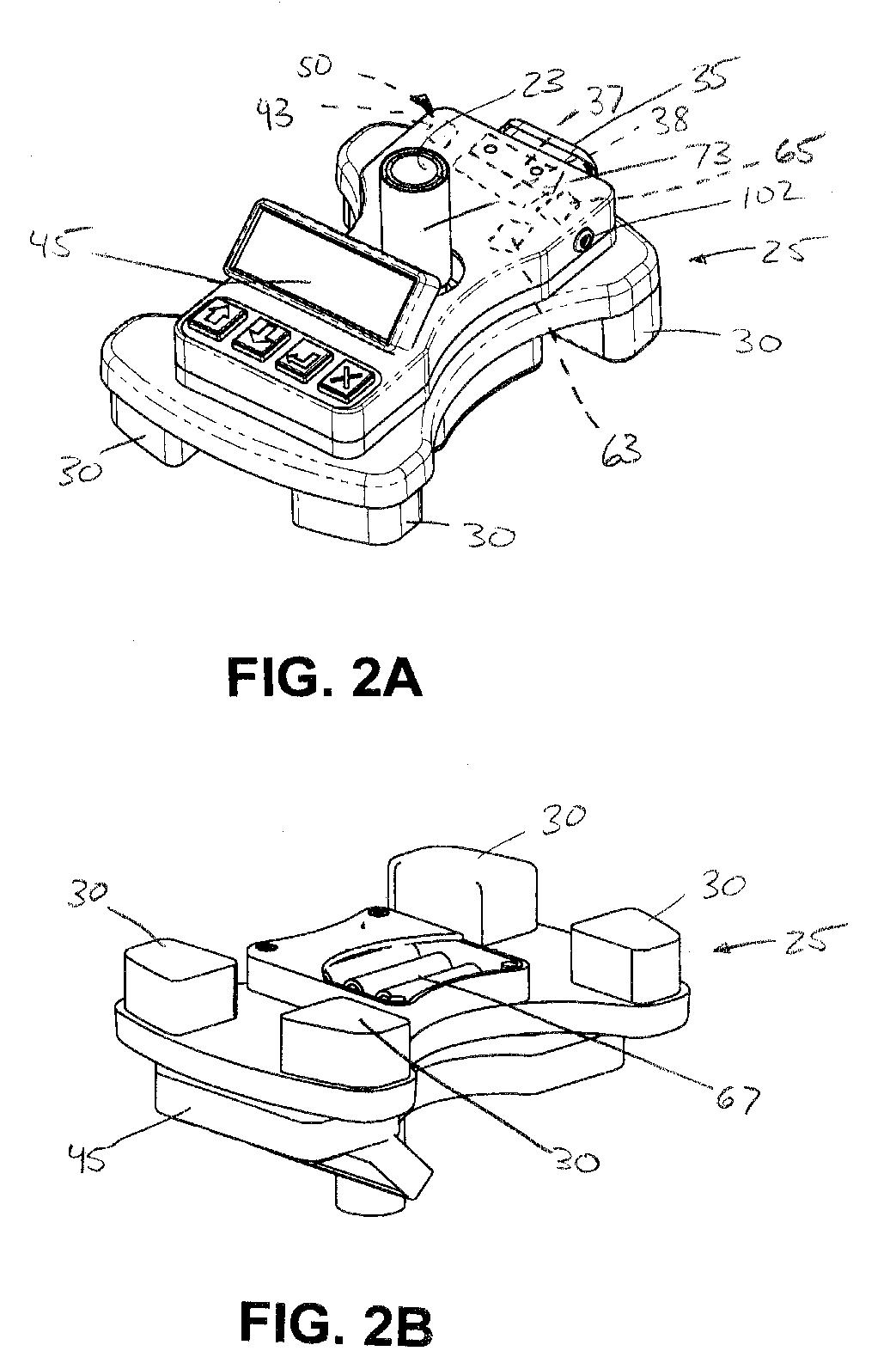
[0011] A walking aid 21 according to an embodiment of the present invention is shown in FIGS. 1A and 1B. The walking aid 21 includes a vertical shaft 23, a base, i.e., a generally horizontal base housing case member 25 disposed at a bottom 27 of the shaft, and a plurality of vertical leg members 29 extending downwardly relative to the horizontal member. As seen in greater detail in FIGS. 2A and 2B, the base housing case member 25 can be in the form of an extra strong and durable injection-molded housing that allows integration of mechanical support, positioning and securing of components, and protection from the elements for equipment such as electrical equipment. Its position at the base distributes the weight at a low center of gravity to enhance the stability of the cane which resists tipping over.

[0012] The legs 29 can be in any suitable form, and may include or be in the form of rubberized solid core feet 30 or caps to enhance friction between the floor and the floor-contactin...


PUM


Abstract

A walking aid includes a vertical shaft, a housing member disposed at a bottom of the shaft, a plurality of vertical leg members extending downwardly relative to the housing member, an electrical component on the walking aid, and control circuitry for the electrical component disposed on the housing member.

Description

BACKGROUND AND SUMMARY [0001] The present invention relates generally to walking aids and, more particularly, to walking aids including controllable electrical features. [0002] It is known to provide items such as lights on walking aids such as canes, safety canes, and walkers to assist users in finding their way around in the dark. Typical walking aids reflect a general lack of consideration to various design features of walking aids, such as how lights should be focused to for practical use, or where controls for electrical equipment on walking aids should be located on the walking aid. It is desirable to provide a walking aid that is designed in view of the actual uses and purposes for the walking aid. [0003] The typical walking aid, largely made of aluminum tubing, has a rather generic appearance. It is desirable to provide a walking aid that can be personalized. [0004] In accordance with an aspect of the present invention, a walking aid comprises a vertical shaft, a housing mem...

Claims


Application Information

Patent Timeline
IPC IPC(8): A45B3/00
CPCA45B3/00A45B9/02A61H2003/0205A61H3/02A45B9/04
Inventor RUSSO, PAUL C.
Owner RUSSO PAUL C
Why Eureka
Try Eureka