Liquid crystal display device and backlight

Active Publication Date: 2007-01-11
PANASONIC LIQUID CRYSTAL DISPLAY CO LTD
View PDF4 Cites 41 Cited by
  • Summary
  • Abstract
  • Description
  • Claims
  • Application Information

AI Technical Summary

Benefits of technology

[0019] With the present invention, when a minimum number of LEDs are provided on the light-receiving surfaces of the light guide plate, generation of brightness variations on the illuminating surface due to lowering of brightness of the LEDs is suppressed, which prevents degradation in display quali

Problems solved by technology

When the number of LEDs is reduced, however, a space between the LEDs arranged opposite to a light-receiving surface of the light guide plate becomes larger, which leads to lowering in brightness of LEDs on the light-receiving surface of the light guide plate due to the effect of the wi

Method used


Image

  • Liquid crystal display device and backlight
  • Liquid crystal display device and backlight
  • Liquid crystal display device and backlight

Examples


first embodiment

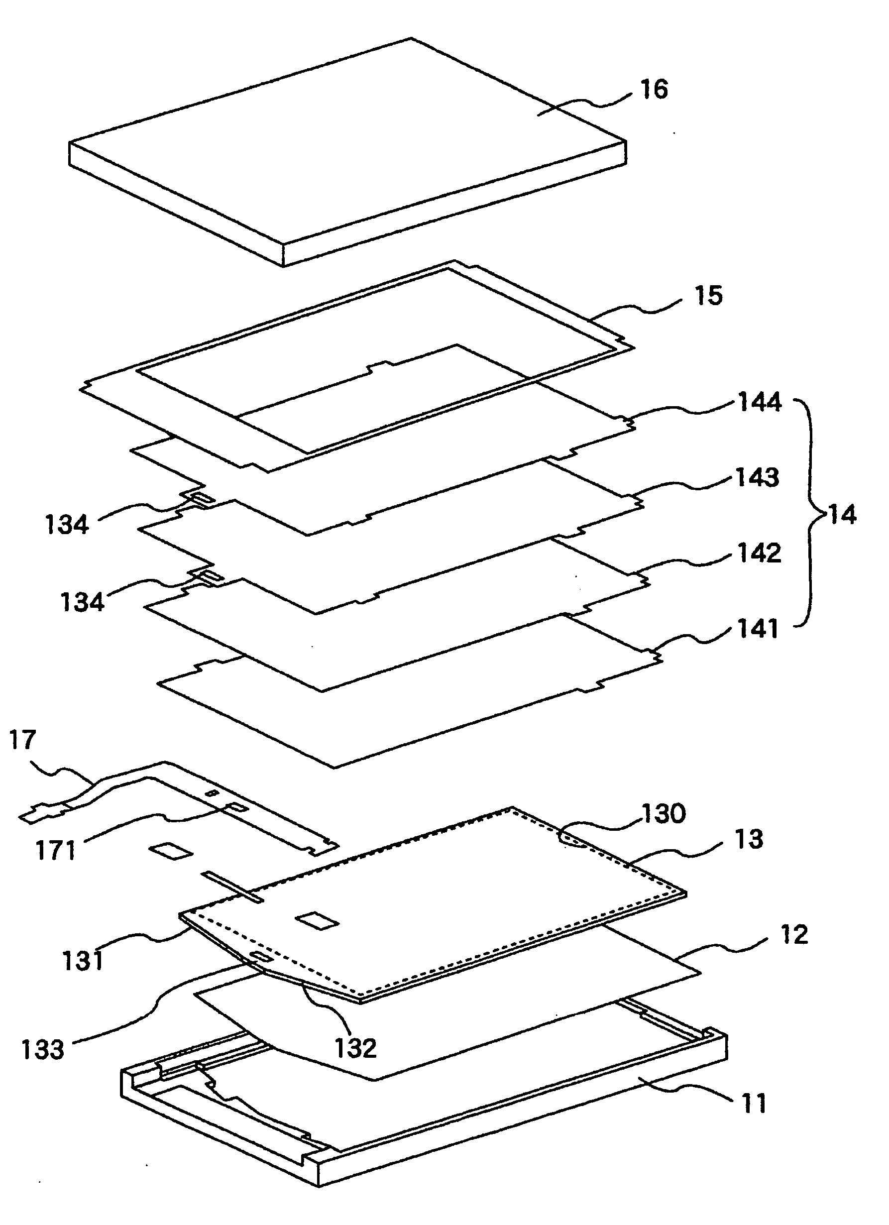
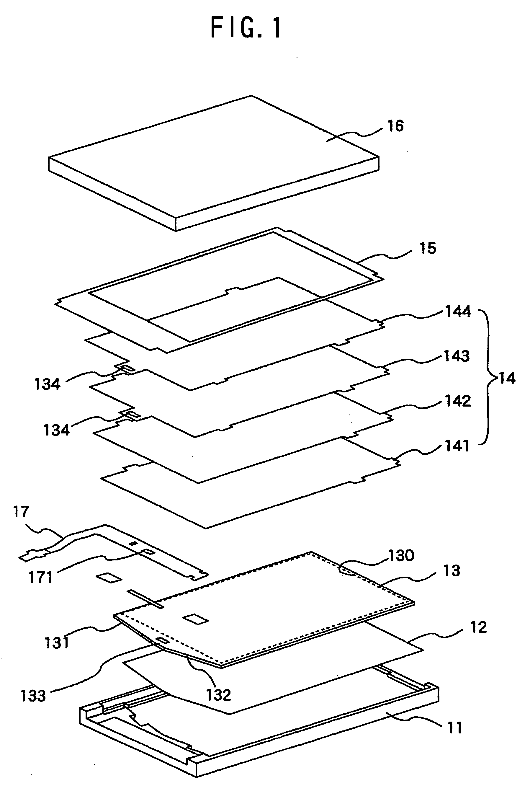
[0031]FIG. 1 is a developed perspective view illustrating the general configuration of a liquid crystal display device according to a first embodiment of the present invention. This liquid crystal display device includes a lower frame 11 made of resin or metal, and a reflecting sheet 12 and a light guide plate 13 provided on the lower frame 11. The device further includes an optical sheets 14 including a plurality of components such as a lower diffusing sheet 141, a lower prism sheet 142, an upper prism sheet 143, and an upper diffusing sheet 144 provided on the light guide plate 13. Furthermore, the device includes a lightproof double-faces tape 15 and a liquid crystal display panel (also referred to as LCD panel) 16 provided on the plurality of optical sheets. An upper frame 11 used to unite the members mentioned above and the lower frame 11 is not shown.

[0032] In this embodiment, the light guide plate 13 has light-receiving surfaces 131, 132, and a surface facing the optical she...


PUM


Abstract

A liquid crystal display device having includes a light guide plate having a surface thereof serving as an illuminating surface region opposite to a liquid crystal display panel, light sources mounted on a flexible printed-circuit board and provided on a side face of the light guide plate, an optical sheet member interposed between the liquid crystal display panel and the light guide plate. The side surfaces of the light guide plate with the light sources provided thereon have a ridge-like inclined surface formed thereon, when viewed from the illuminating surface, and the ridge-like inclined surfaces serve as a light-receiving surface with the light source arranged thereon.

Description

CLAIM OF PRIORITY [0001] The present application claims priority from Japanese Application JP 2005-200455 filed on Jul. 8, 2005, the content of which is hereby incorporated by reference into this application. FIELD OF THE INVENTION [0002] The present invention relates generally to liquid crystal display devices and backlight systems for the same. More specifically, the invention relates to a liquid crystal device that has an illuminating system suitably provided on a side face of a light guide plate with a point light source comprising a solid state light-emitting element such as a light-emitting diode as a luminous source for a liquid crystal display panel. BACKGROUND OF THE INVENTION [0003] A power-saving and light-weight liquid crystal display device is often used as a display device in a compact information terminal such as a mobile telephone or a PDA. Examples of liquid crystal display devices include those that make use of external light as a lighting means for visualizing a l...

Claims


Application Information

Patent Timeline
IPC IPC(8): G02F1/1335G02F1/1333
CPCG02B6/0018G02B6/0038G02B6/0083H05K1/189G02F1/133615G02F1/13452G02B6/009G02F1/1333G02F1/1335
Inventor TAKAHASHI, YOSHIAKIKURIHARA, MASAHIKOMIFUNE, MASAYUKIKAGABU, KEN
Owner PANASONIC LIQUID CRYSTAL DISPLAY CO LTD
Why Eureka
Try Eureka