Method for driving liquid crystal display apparatus

a liquid crystal display and display technology, applied in the field of methods for driving liquid crystal display apparatuses, can solve the problems of long completion time, low response speed of liquid crystal display apparatus, etc., and achieve the effect of improving response speed, easy to discriminate, and without impairing characteristics

Inactive Publication Date: 2009-03-26
SHARP KK
View PDF6 Cites 17 Cited by
  • Summary
  • Abstract
  • Description
  • Claims
  • Application Information

AI Technical Summary

Benefits of technology

[0024]This makes it possible to provide a method for driving a liquid crystal display apparatus 10, which method makes it easy to discriminate between a still image and a moving image by acquiring a signal for discriminating between a still image and a moving image. When a still image is displayed,

Problems solved by technology

Conventionally, a liquid crystal display apparatus has had a problem of low response speed.
Moreover, the low response speed of the liquid crystal display apparatus is attributed to the fact that it takes a long time to complete the change caused in orientation state of the liquid crystal molecules in response to the change in voltage applied to the liquid crystal layer.
On the other hand, high-quality picture technologies often cause a decrease in response speed simultaneously (e.g., AVS and mobile AVS).
However, as shown in FIG. 9, such a method causes deterioration in image quality.
However, a change in overdrive amount only causes a change in size of the left angular portion, and does not result in an improvement in the right sloping portion.
Therefore, there is no improvement in display.
Further, as described above, an e

Method used


Image

  • Method for driving liquid crystal display apparatus
  • Method for driving liquid crystal display apparatus
  • Method for driving liquid crystal display apparatus

Examples


Embodiment Construction

[0039]An embodiment of the present invention will be described below with reference to FIGS. 1 to 8.

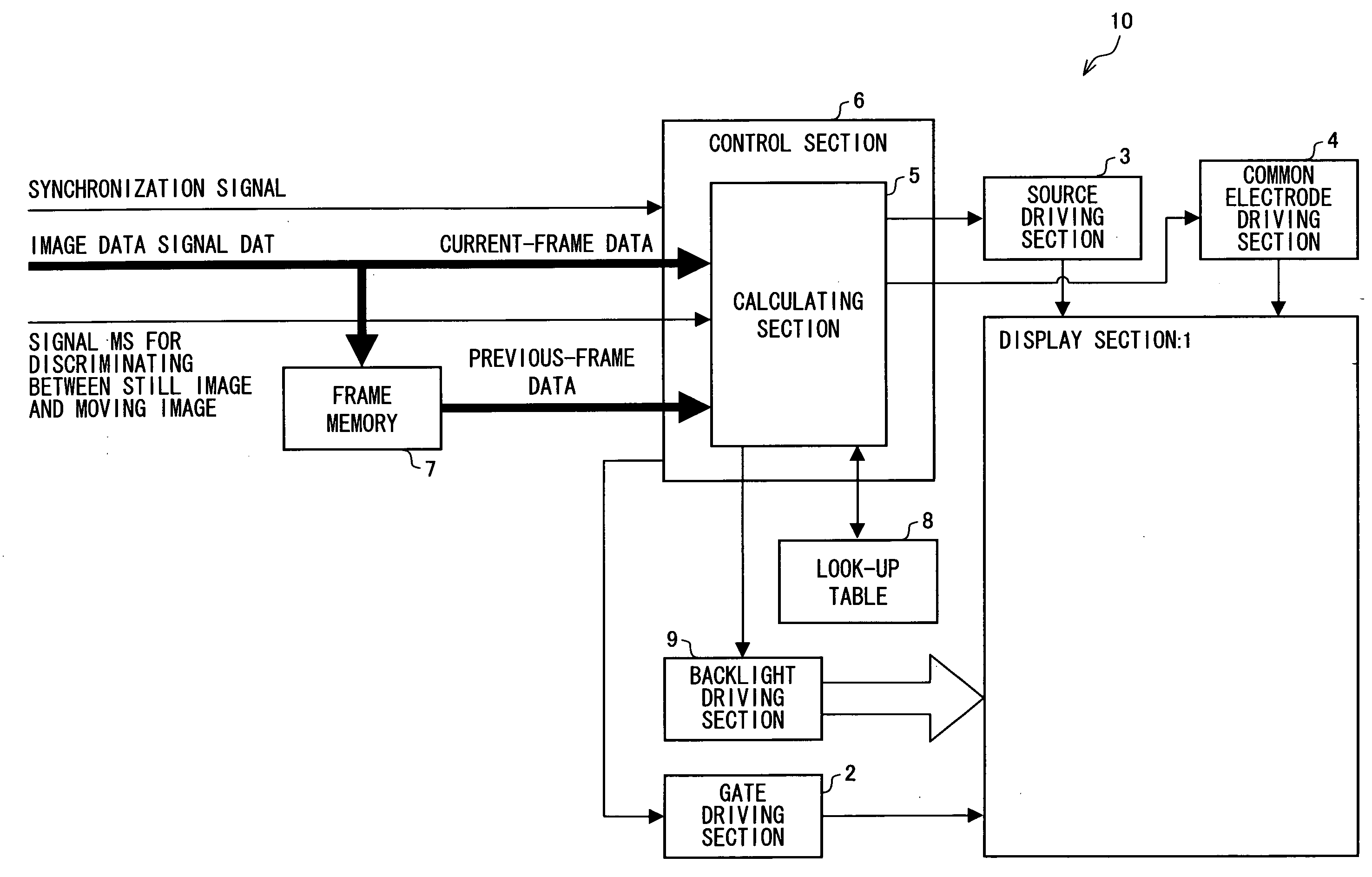
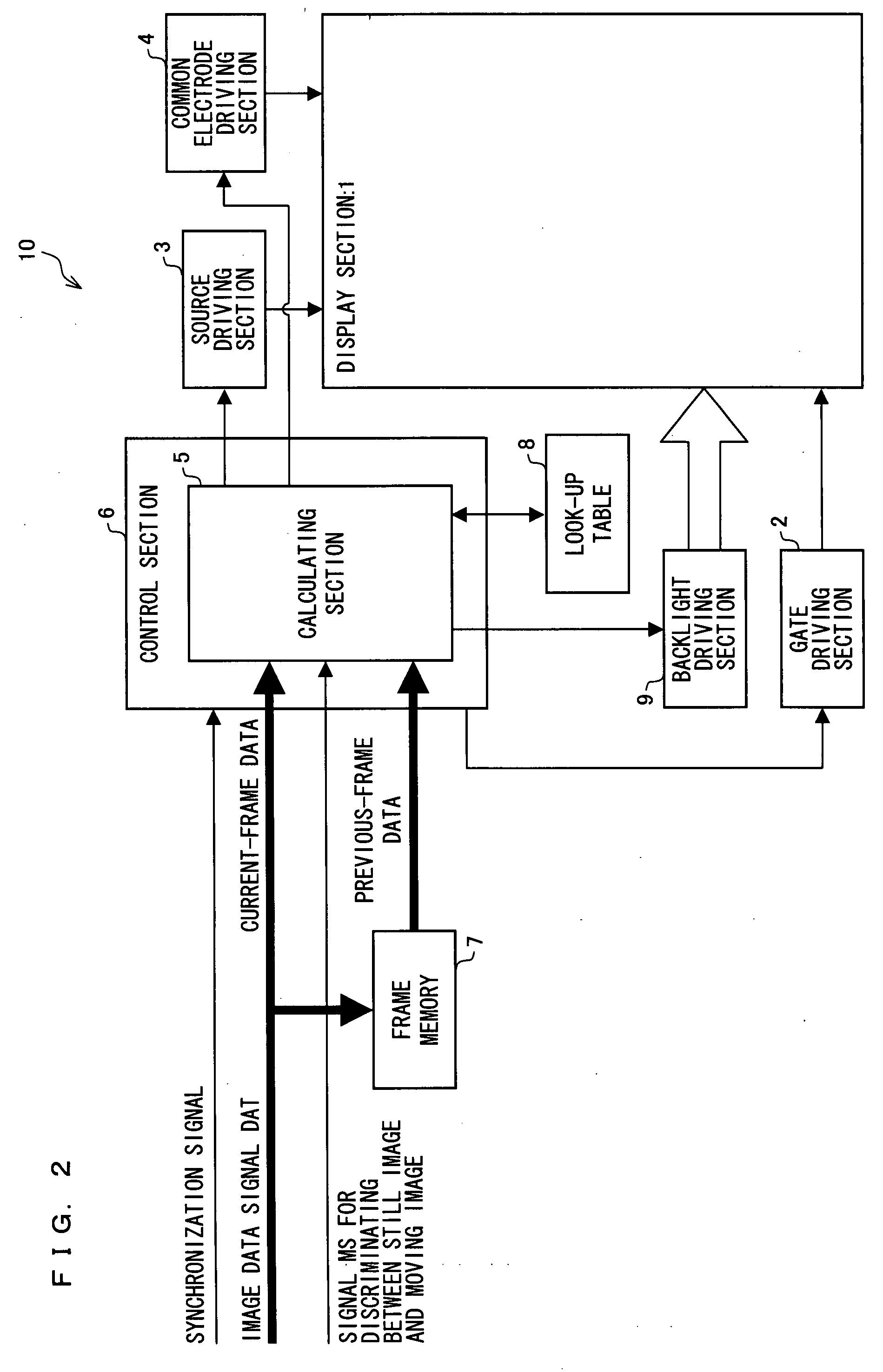
[0040]For example, as shown in FIG. 2, an active matrix liquid crystal display apparatus 10 of the present embodiment includes: a display section 1, a gate driving section 2, a source driving section 3, a common electrode driving section 4, a control section in which a calculating section 5 is provided, a frame memory 7, a look-up table 8, and a backlight driving section 9.

[0041]Although not fully shown in the figure, the display section 1 includes e scanning signal lines that are parallel to one another, f data signal lines that are parallel to one another, and pixels arrayed in a matrix manner. Each of the pixels is formed in a region enclosed by two adjacent scanning signal lines and two adjacent data signal lines.

[0042]The gate driving section 2 sequentially generates, in accordance with a gate clock signal and a gate start pulse each outputted from the control section 6, scanning...


PUM


Abstract

In one embodiment of the present invention, when a still image is displayed, applied voltages respectively corresponding to a total of n (n being an integer of not less than 4) types of gradation 0 to (n−1) are outputted to pixels. On the other hand, when a moving image is displayed, an applied voltage corresponding to a predetermined gradation m (1≦m≦(n−2)) is applied to the pixels instead of applied voltages respectively corresponding to gradations of less than the predetermined gradation m.

Description

TECHNICAL FIELD[0001]The present invention relates to methods for driving liquid crystal display apparatuses. Particularly, the present invention relates to a method for driving a liquid crystal display apparatus, which method makes it possible to achieve an improvement in response speed at which a moving image is displayed.BACKGROUND ART[0002]Conventionally, a liquid crystal display apparatus has had a problem of low response speed. That is, a change in display gradation of the liquid crystal display apparatus is such that: a change in orientation state of liquid crystal molecules is made by making a change in voltage applied to a liquid crystal layer, so that the transmittance of a display pixel is changed. Moreover, the low response speed of the liquid crystal display apparatus is attributed to the fact that it takes a long time to complete the change caused in orientation state of the liquid crystal molecules in response to the change in voltage applied to the liquid crystal lay...

Claims


Application Information

Patent Timeline
IPC IPC(8): G09G3/36
CPCG09G3/3406G09G3/3696G09G2320/0252G09G2340/16G09G2320/0613G09G2320/066G09G2320/0673G09G2320/0271
Inventor YAMATO, ASAHIKAWASHIMA, YUKINAKAGAWA, KIYOSHITAKAHASHI, KOHZOHYANAGI, TOSHIHIRO
Owner SHARP KK
Why Eureka
Try Eureka