Micro neutron detectors

a technology of neutron detectors and micro-nuclear particles, which is applied in the field of radiological detectors, can solve the problems of clear lack of such coatings in the openings, and achieve the effect of easy discrimination

Inactive Publication Date: 2006-02-02
KANSAS STATE UNIV RES FOUND
View PDF0 Cites 31 Cited by
  • Summary
  • Abstract
  • Description
  • Claims
  • Application Information

AI Technical Summary

Benefits of technology

[0030] 3. Gamma ray insensitive—gas-filled or gas-flow detectors are typically insensitive to gamma rays. The large signals produced by the fission fragments will be easily discriminated from any gamma ray events.
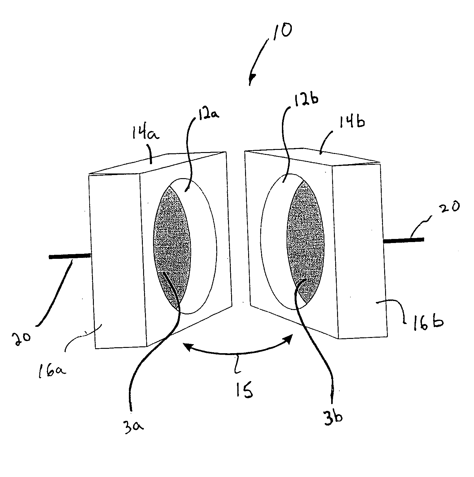
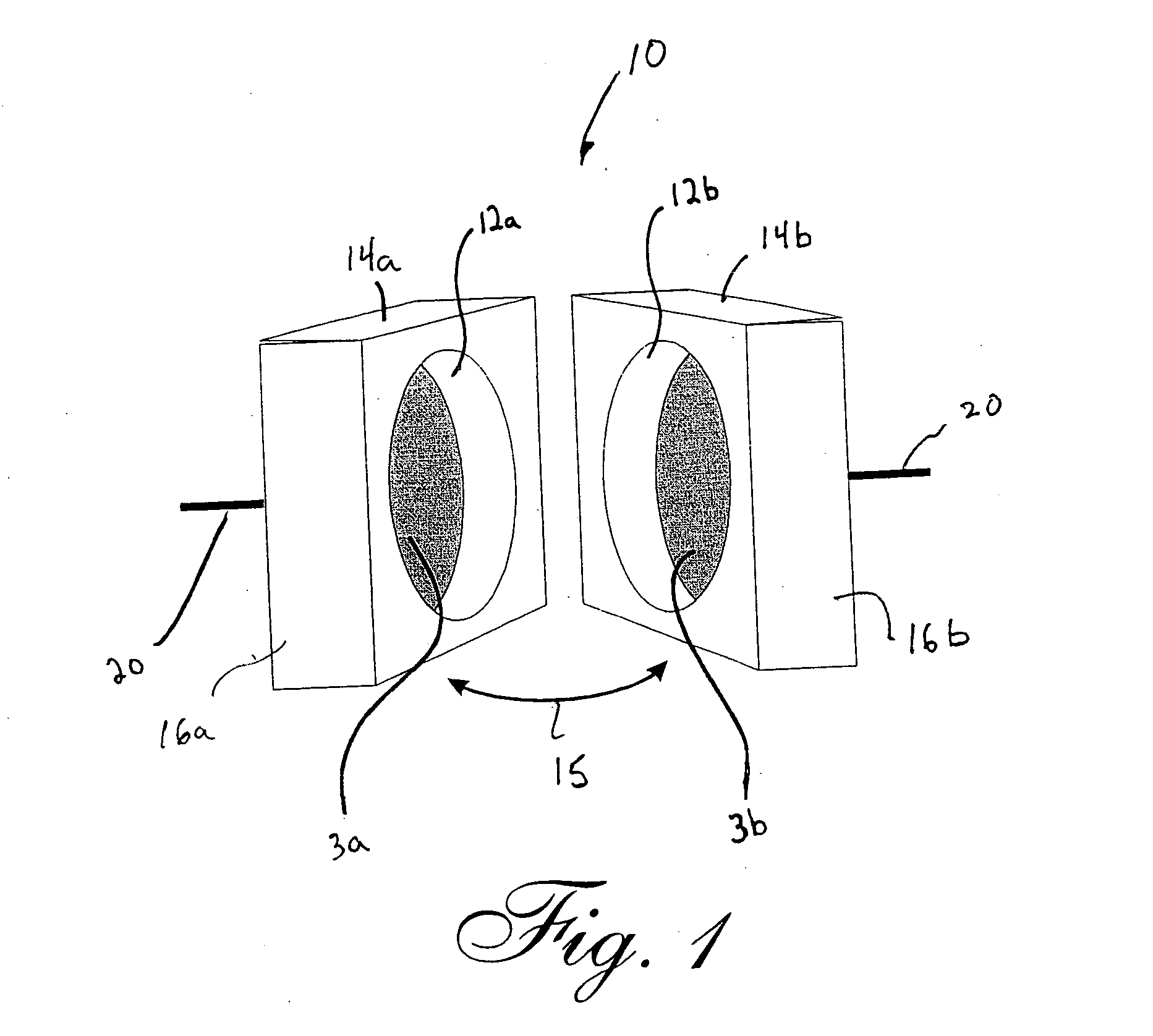
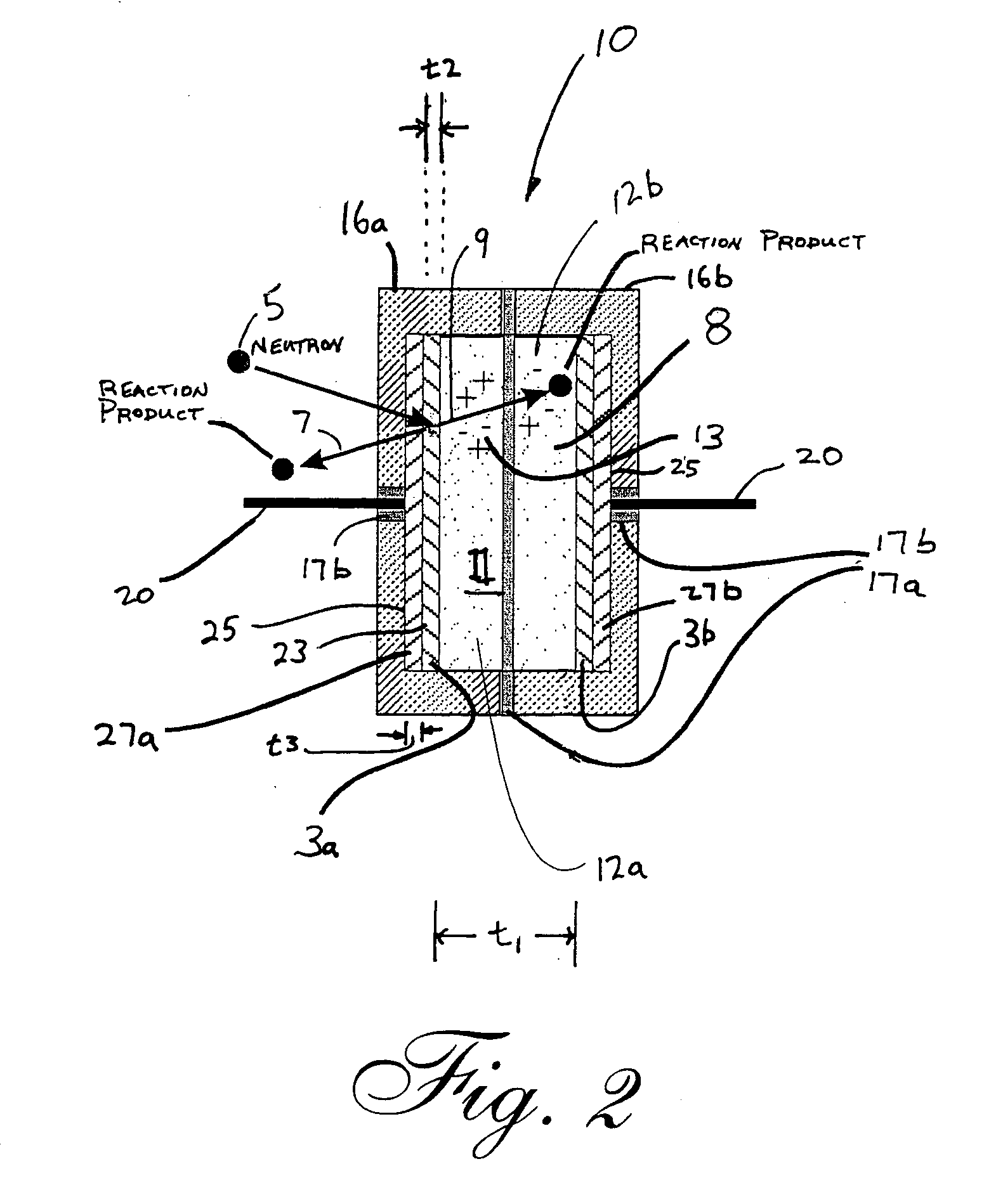
[0031] 4. No cross talk—pockets as capillary channels have walls substantially preventing charges from entering adjacent regions.

Problems solved by technology

However, one of the openings clearly lacks such coatings.

Method used


Image

  • Micro neutron detectors
  • Micro neutron detectors
  • Micro neutron detectors

Examples


example

[0091] Prototype micro neutron detectors were manufactured from machined aluminum oxide (alumina) pieces, and each detector was embodied as a plurality of three fastened supports, such as representatively shown in FIGS. 3-5. The interior support included an opening that, when fastened to the exterior supports, defined a generally cylindrical gas pocket having a 2-mm diameter and 1-mm thickness. To make the detector, compositions of Ti / Au were evaporated on each of the exterior supports to form an alumina cathode and anode. In turn, the support having the cathode was aligned and fastened to the interior support with an epoxy. A dilute solution of Uranyl-Nitrate (neutron reactive material) was then applied over the Ti / Au forming the cathode and baked with an infrared lamp for 5 minutes. Afterwards, the fastened interior support and the exterior support forming the cathode, including the baked uranyl-nitrate, were inserted into a glove box, of sorts, which was backfilled with P-10 gas....


PUM


Abstract

Micro neutron detectors include relatively small pockets of gas including a neutron reactive material. During use, under a voltage bias in a neutron environment, neutron interactions in the neutron reactive material are seen to occur. Ultimately, electron-ion pairs form and positive ions drift to a cathode and electrons to the anode. The motion of charges then produces an induced current that is sensed and measurable, thereby indicating the presence of neutrons. Preferred pocket volumes range from a few cubic microns to about 1200 mm3; neutron reactive materials include fissionable, fertile or fissile material (or combinations), such as 235U, 238U, 233U, 232Th, 239Pu, 10B, 6Li and 6LiF; gasses include one or more of argon, P-10, 3He, BF3, BF3, CO2, Xe, C4H10, CH4, C2H6, CF4, C3H8, dimethyl ether, C3H6 and C3H8. Arrangements include two- and three-piece sections, arrays (including or not triads capable of performing multiple detecting functions) and/or capillary channels.

Description

[0001] This application claims priority to and the benefit of U.S. Provisional Application Ser. No. 60 / 592,314, filed Jul. 29, 2004.STATEMENT OF GOVERNMENT RIGHTS [0002] The invention was partially funded by the U.S. Government, under the Department of Energy, Nuclear Energy Research Initiative (NERI) Grant Number DE-FG03-02SF22611. Accordingly, the U.S. Government may reserve certain rights to its use.FIELD OF THE INVENTION [0003] This invention relates generally to radiation detectors. In particular, the invention relates to semiconductor detectors designed to detect neutrons of various energy ranges. More particularly, the invention relates to micro neutron detectors useful for the real-time monitoring of both near-core and in-core neutron fluxes of nuclear reactors. BACKGROUND OF THE INVENTION [0004] Nuclear reactors convert mass into energy. Although nuclear fusion provides an alternative means of energy production, limitations in scientific understanding currently limit energy...

Claims


Application Information

Patent Timeline
Patent Type & Authority Applications(United States)
IPC IPC(8): G21G1/06
CPCG01T1/167G01T1/185G01T3/00G21C17/108G21Y2004/30G21Y2002/204G21Y2002/301G21Y2002/304G21Y2004/10G21Y2002/201Y02E30/30
Inventor MCGREGOR, DOUGLAS S.OHMES, MARTIN F.SHULTIS, JOHN K.
Owner KANSAS STATE UNIV RES FOUND
Why Eureka
Try Eureka