Liquid crystal display device and backlight

a technology of liquid crystal display device and backlight, which is applied in the direction of instrumentation, lighting and heating apparatus, planar/plate-like light guides, etc., can solve the problems of reducing the brightness of leds on the light-receiving surface of the light-guide plate, reducing the suitable holding structure of conventional technology, and reducing the cost of the backlight system using the surface-mounted type of leds. , to achieve the effect of preventing degradation of display quality, reducing

Active Publication Date: 2009-08-04
PANASONIC INTELLECTUAL PROPERTY CORP OF AMERICA +1
View PDF9 Cites 16 Cited by
  • Summary
  • Abstract
  • Description
  • Claims
  • Application Information

AI Technical Summary

Benefits of technology

[0007]Also the backlight system using LEDS as light sources is required to reduce costs. One of effective means for meeting the requirement is conceived to reduce the number of LEDs. When the number of LEDs is reduced, however, a space between the LEDs arranged opposite to a light-receiving surface of the light guide plate becomes larger, which leads to lowering in brightness of LEDs on the light-receiving surface of the light guide plate due to the effect of the widening space. This generates brightness variations on the illuminating surface, with the result that the display quality disadvantageously becomes lower.
[0010]An object of the present invention is to provide a liquid crystal display device capable of preventing degradation of display quality, when a minimum number of LEDs are provided on the light-receiving surface of the light guide plate, by suppressing in-plane brightness variations on the illuminating surface due to brightness-lowering among the LEDs. More specifically, an object of the present invention is to provide a backlight system (lighting system) capable of preventing the illuminating surface from being locally darkened due to lowering of brightness of LEDs and also capable of preventing generation of brightness variations even when the number of LEDs is reduced to reduce cost of a backlight system using the surface-mounted types of LEDs, and also to provide a liquid crystal display device using the lighting system.
[0019]With the present invention, when a minimum number of LEDs are provided on the light-receiving surfaces of the light guide plate, generation of brightness variations on the illuminating surface due to lowering of brightness of the LEDs is suppressed, which prevents degradation in display quality. With the present invention, cost of the backlight system using the surface-mounted type of LEDs can be reduced, and even when the number of LEDs is reduced, it never occurs that brightness of the LEDs lowers to locally darken the illuminating surface and that brightness variations are generated.

Problems solved by technology

When the number of LEDs is reduced, however, a space between the LEDs arranged opposite to a light-receiving surface of the light guide plate becomes larger, which leads to lowering in brightness of LEDs on the light-receiving surface of the light guide plate due to the effect of the widening space.
This generates brightness variations on the illuminating surface, with the result that the display quality disadvantageously becomes lower.
The conventional technology does not take into account the holding structure most suitable for use of the surface-mounted type of LEDs.

Method used


Image

  • Liquid crystal display device and backlight
  • Liquid crystal display device and backlight
  • Liquid crystal display device and backlight

Examples


first embodiment

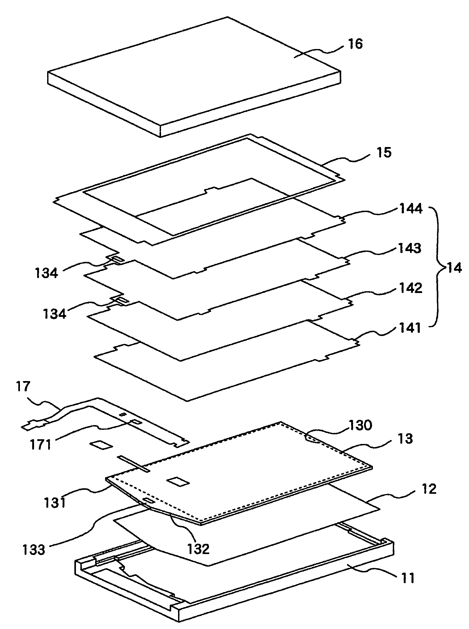
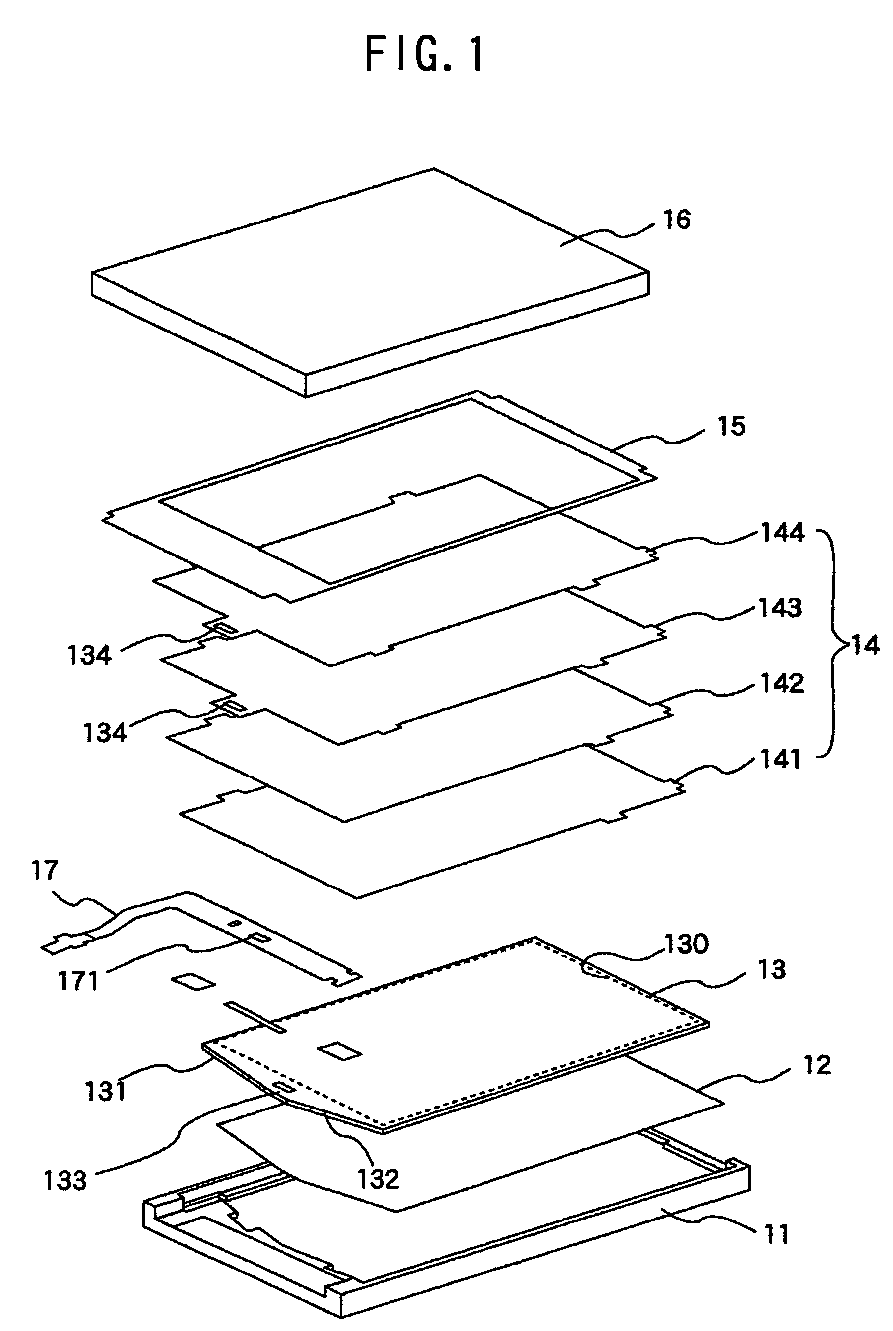
[0031]FIG. 1 is a developed perspective view illustrating the general configuration of a liquid crystal display device according to a first embodiment of the present invention. This liquid crystal display device includes a lower frame 11 made of resin or metal, and a reflecting sheet 12 and a light guide plate 13 provided on the lower frame 11. The device further includes an optical sheets 14 including a plurality of components such as a lower diffusing sheet 141, a lower prism sheet 142, an upper prism sheet 143, and an upper diffusing sheet 144 provided on the light guide plate 13. Furthermore, the device includes a lightproof double-faces tape 15 and a liquid crystal display panel (also referred to as LCD panel) 16 provided on the plurality of optical sheets. An upper frame 11 used to unite the members mentioned above and the lower frame 11 is not shown.

[0032]In this embodiment, the light guide plate 13 has light-receiving surfaces 131, 132, and a surface facing the optical sheet...


PUM

PropertyMeasurementUnit
sizeaaaaaaaaaa
flexibleaaaaaaaaaa
lengthaaaaaaaaaa

Abstract

A liquid crystal display device having includes a light guide plate having a surface thereof serving as an illuminating surface region opposite to a liquid crystal display panel, light sources mounted on a flexible printed-circuit board and provided on a side face of the light guide plate, an optical sheet member interposed between the liquid crystal display panel and the light guide plate. The side surfaces of the light guide plate with the light sources provided thereon have a ridge-like inclined surface formed thereon, when viewed from the illuminating surface, and the ridge-like inclined surfaces serve as a light-receiving surface with the light source arranged thereon.

Description

CLAIM OF PRIORITY[0001]The present application claims priority from Japanese Application JP 2005-200455 filed on Jul. 8, 2005, the content of which is hereby incorporated by reference into this application.FIELD OF THE INVENTION[0002]The present invention relates generally to liquid crystal display devices and backlight systems for the same. More specifically, the invention relates to a liquid crystal device that has an illuminating system suitably provided on a side face of a light guide plate with a point light source comprising a solid state light-emitting element such as a light-emitting diode as a luminous source for a liquid crystal display panel.BACKGROUND OF THE INVENTION[0003]A power-saving and light-weight liquid crystal display device is often used as a display device in a compact information terminal such as a mobile telephone or a PDA. Examples of liquid crystal display devices include those that make use of external light as a lighting means for visualizing a latent im...

Claims


Application Information

Patent Timeline
Patent Type & Authority Patents(United States)
IPC IPC(8): G02F1/1335F21V7/04
CPCG02B6/0018G02B6/009G02B6/0038G02B6/0083H05K1/189G02F1/133615G02F1/13452G02F1/1333G02F1/1335
Inventor TAKAHASHI, YOSHIAKIKURIHARA, MASAHIKOMIFUNE, MASAYUKIKAGABU, KEN
Owner PANASONIC INTELLECTUAL PROPERTY CORP OF AMERICA
Why Eureka
Try Eureka