Steering control sensor for an automatic vacuum cleaner

a technology of automatic vacuum cleaner and control sensor, which is applied in the direction of vacuum cleaners, automatic obstacle detection, domestic applications, etc., can solve the problems of high cost of automatic vacuum cleaner and heavy work of cleaning one's own hous

Inactive Publication Date: 2007-01-25
YAN JASON
View PDF7 Cites 146 Cited by
  • Summary
  • Abstract
  • Description
  • Claims
  • Application Information

AI Technical Summary

Benefits of technology

[0005] The present invention has been accomplished under the circumstances in view. It is the main object of the present invention to provide a steering control sensor for automatic vacuum cleaner, which automatically drives the automatic vacuum cleaner to change the steering direction when the automatic vacuum cleaner reaches a floor edge or encounters an obstacle. To achieve this and other objects of the present invention, the steering control sensor is installed in an automatic vacuum cleaner and electrically connected to a central processing unit of the automatic vacuum cleaner for driving the automatic vacuum cleaner to change the steering direction when the automatic vacuum cleaner reaches a floor edge or is stopped against an obstacle or a wall during movement on the floor. The steering control sensor comprises a casing mounted in the automatic vacuum cleaner, a circuit board mounted inside the casing, a light emitting device installed in the circuit boar

Problems solved by technology

Therefore, cleaning one's own house is a heavy work to most people.
Because multiple infrared t

Method used


Image

  • Steering control sensor for an automatic vacuum cleaner
  • Steering control sensor for an automatic vacuum cleaner
  • Steering control sensor for an automatic vacuum cleaner

Examples


Embodiment Construction

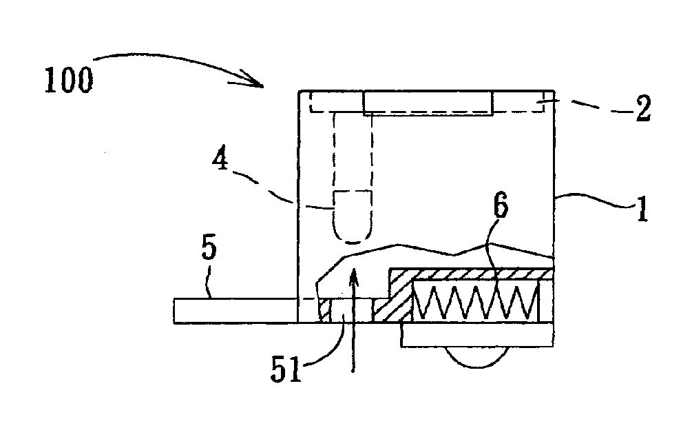
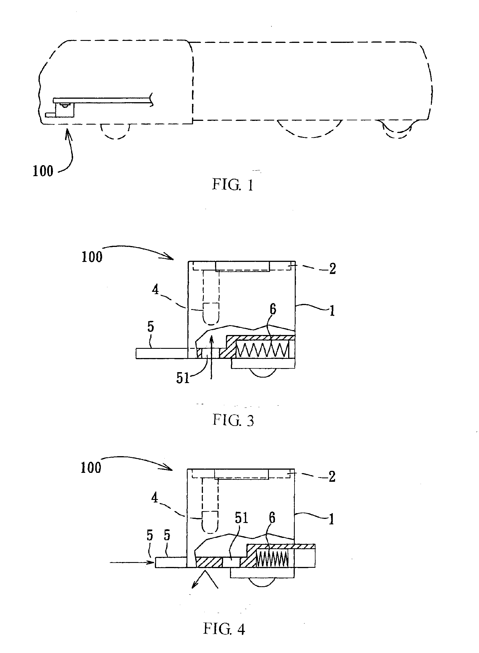
[0010] Referring to FIG. 1, a steering control sensor 100 is installed in the front bottom side of an automatic vacuum cleaner to detect the surroundings. The steering control sensor 100 outputs a signal to the CPU (not shown) of the automatic vacuum cleaner when the automatic vacuum cleaner moves to a floor edge or is stopped against an obstacle or a wall, causing the CPU to change the steering direction of the automatic vacuum cleaner.

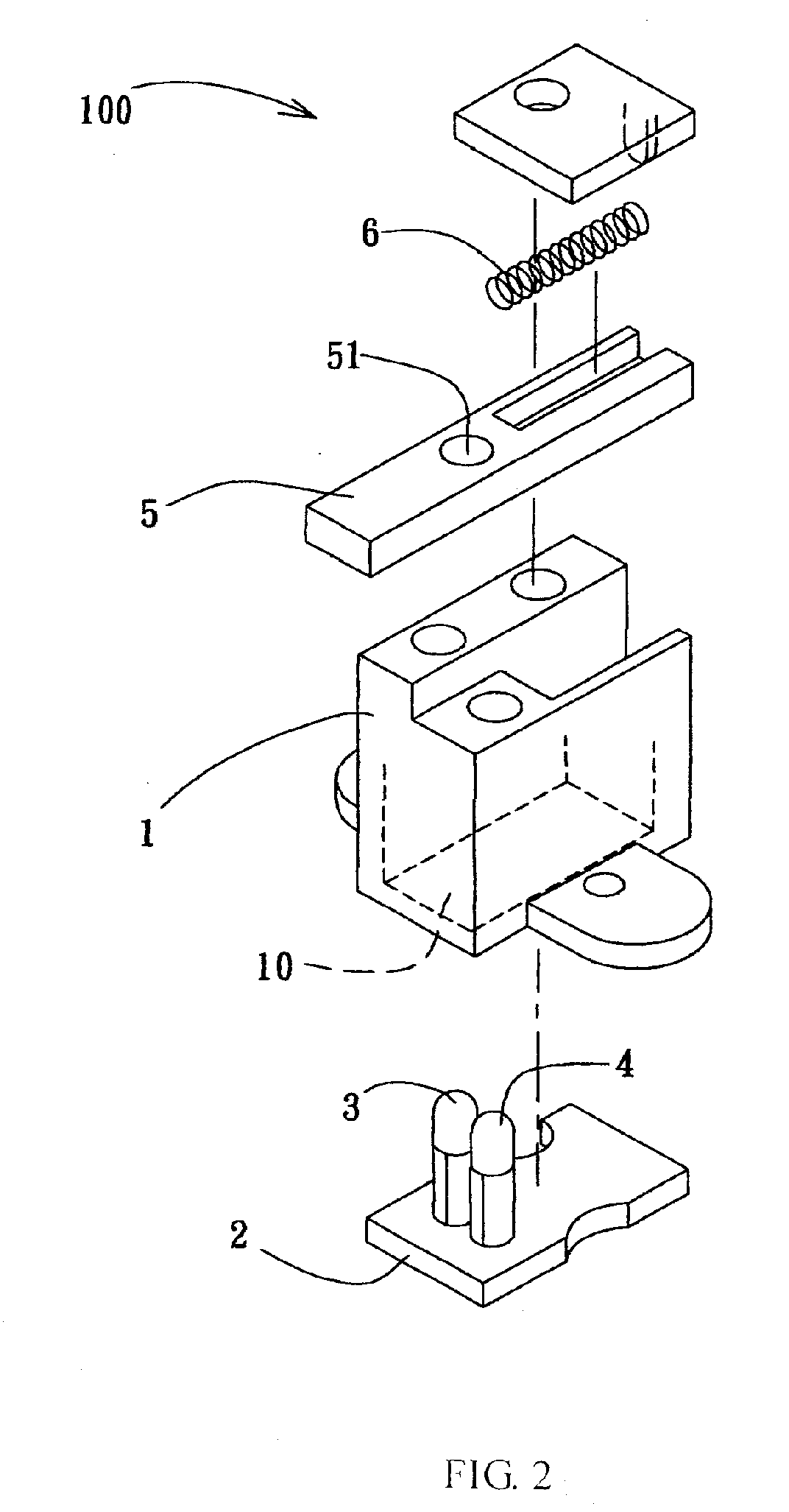
[0011] Referring to FIGS. 2˜4, the steering control sensor 100 comprises a casing 1, a circuit device 2, a light emitting device 3, a photo sensor 4, and a contact member 5.

[0012] The casing 1 is mounted in the front bottom side of the vacuum cleaner, defining an accommodating chamber 10.

[0013] The circuit device 2 is a circuit board mounted inside the accommodating chamber 10 of the casing 1.

[0014] The light emitting device 3 according to this embodiment is a LED (light emitting diode) soldered to the circuit board 2 and adapted to emit light on...


PUM


Abstract

A steering control sensor installed in an automatic vacuum cleaner for controlling the steering direction of the automatic vacuum cleaner is disclosed to include a LED for emitting light onto the floor to produce a reflected light signal, a photo sensor for receiving the light signal, and a spring-supported contact member, which allows the photo sensor to receive the light signal when the automatic vacuum cleaner encounters no obstacle when moving on the floor, or blocks the light signal from the photo sensor to cause the photo sensor to output a signal to drive the automatic vacuum cleaner to change the steering direction when the automatic vacuum cleaner encounters an obstacle during movement.

Description

BACKGROUND OF THE INVENTION [0001] 1, Field of the Invention [0002] The present invention relates to an automatic vacuum cleaner and more specifically to a control sensor for use in an automatic vacuum cleaner to control the steering of the automatic vacuum cleaner. [0003] 2. Description of the Related Art [0004] Most people spend a lot of time in working and have a relatively shorter time for entertainment. Therefore, cleaning one's own house is a heavy work to most people. In order to help people clean the house without labor, automatic vacuum cleaners have been developed. These automatic vacuum cleaners move on the floor automatically, and draw in air and dust together when moving on the floor. Similar designs are seen in Taiwan Patent Nos. 7220383 and M247107. An automatic vacuum cleaner has multiple infrared transmitters and receivers for detecting a floor edge or an obstacle in the traveling path. Because multiple infrared transmitters and infrared receivers are used, the cost...

Claims


Application Information

Patent Timeline
IPC IPC(8): A47L5/00
CPCA47L2201/04A47L9/009
Inventor YAN, JASON
Owner YAN JASON
Why Eureka
Try Eureka