Arc start control method in robot welding

a robot welding and control method technology, applied in the direction of arc welding apparatus, welding apparatus, manufacturing tools, etc., can solve the problems of wire tip adhesion to the base metal, small vibration, abrupt change in the position of the wire tip, etc., and achieve the effect of improving the arc starting

Active Publication Date: 2007-02-01
DAIHEN CORP
View PDF3 Cites 3 Cited by
  • Summary
  • Abstract
  • Description
  • Claims
  • Application Information

AI Technical Summary

Benefits of technology

[0016] Thus, the present invention provides an arc start control method in robot welding capable of preventing re-shorting right after the initial arcing and providing good arc starting.
[0018] Such a method enables rapid increase in the arc length through the application of the re-shorting prevention current which has a large value, upon generation of the initial arc. This enables to prevent re-shorting between the wire tip and the base metal even if there is an abrupt positional change of the wire tip caused by the above-described play or vibration, enabling to achieve a good arc starting.
[0020] Such a method enables to adjust the arc length to an appropriate value at the end of the re-shorting prevention period, through a variable control of the re-shorting prevention period based on the arc voltage, enabling to further improve the arc starting.
[0022] Such a method enables to adjust the arc length to an appropriate value at the ending of the re-shorting prevention period, through a variable control of the re-shorting prevention current based on the arc voltage, enabling to further improve the arc starting.

Problems solved by technology

Further, as the robot moves, there is always small vibration, and the welding torch also vibrates during the retracting movement.
Similarly, the vibration of the welding torch also causes an abrupt change in the wire tip position.
The re-shorting does, however; since the initial arc has already made a molten on the wire tip surface, the re-shorting will cause the wire tip to adhere to the base metal.
When this happens, a large electric current of a few hundreds of amperes is necessary in order to break the adhesion, resulting in poor arc start with a large amount of spatters.

Method used


Image

  • Arc start control method in robot welding
  • Arc start control method in robot welding
  • Arc start control method in robot welding

Examples


embodiment 1

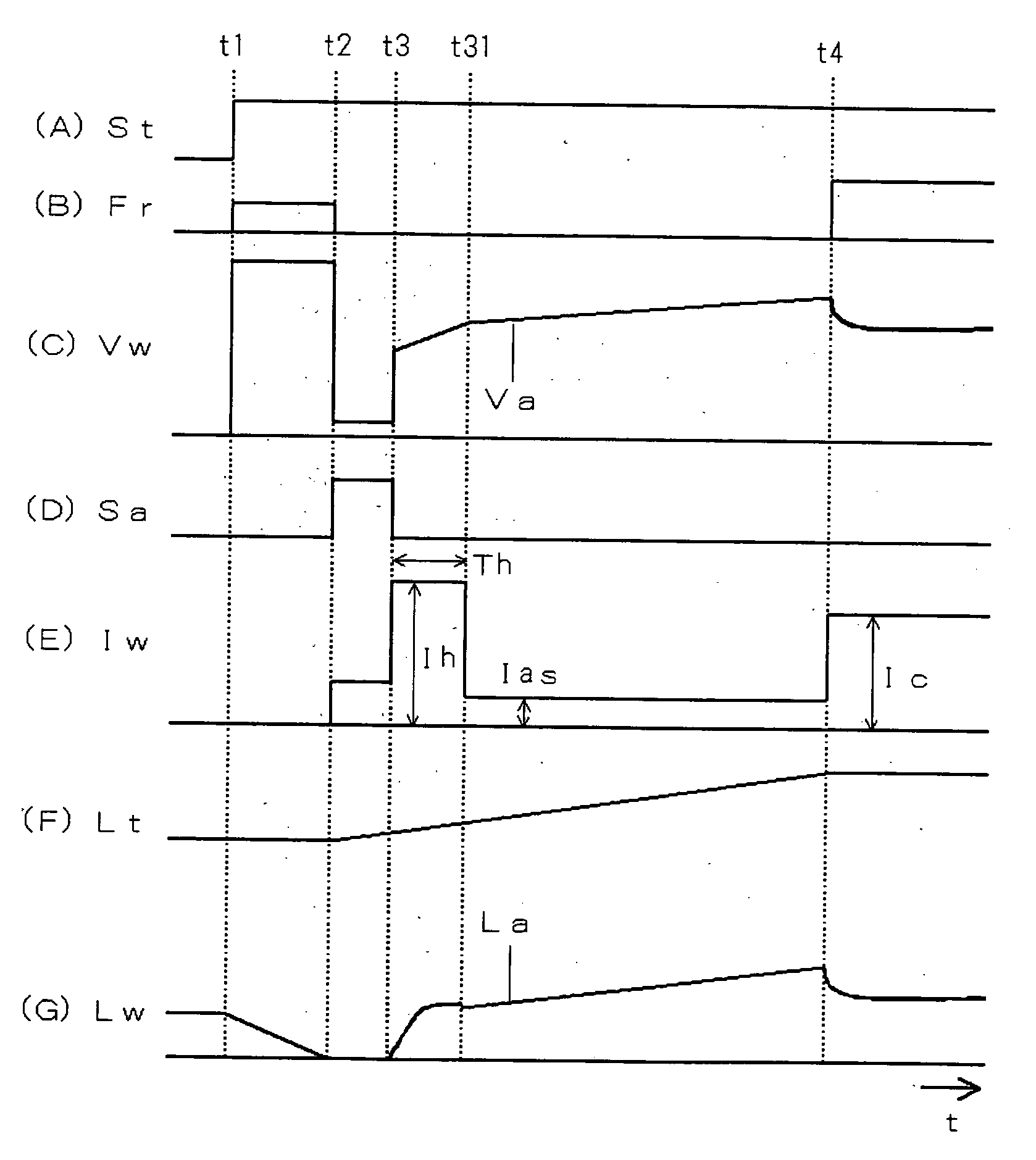
[0030]FIG. 1 is a timing chart of an arc start control method in robot welding according to Embodiment 1 of the present invention. In the figure, (A), (B), (C), (D), (E), (F), and (G) show time course changes of a welding start signal St, a feeding rate setting signal Fr, a welding voltage Vw, a short / arc determination signal Sa, a welding current Iw, a chip-to-base-metal distance Lt, and a wire-tip-to-base-metal distance Lw (=arc length La), respectively. The embodiment uses a welder having the same configuration as described with reference to FIG. 5 above. FIG. 1 corresponds to FIG. 6, and illustrates the same operations up to Time Point t3, so these will not be described again. Hereinafter, description will cover operations at and after Time Point t3.

[0031] At Time Point t3, as shown by (G), as the retracting movement of the welding torch creates a gap between the wire tip and the base metal, an initial arc is generated. As shown by (C), the welding voltage Vw increases to becom...

embodiment 2

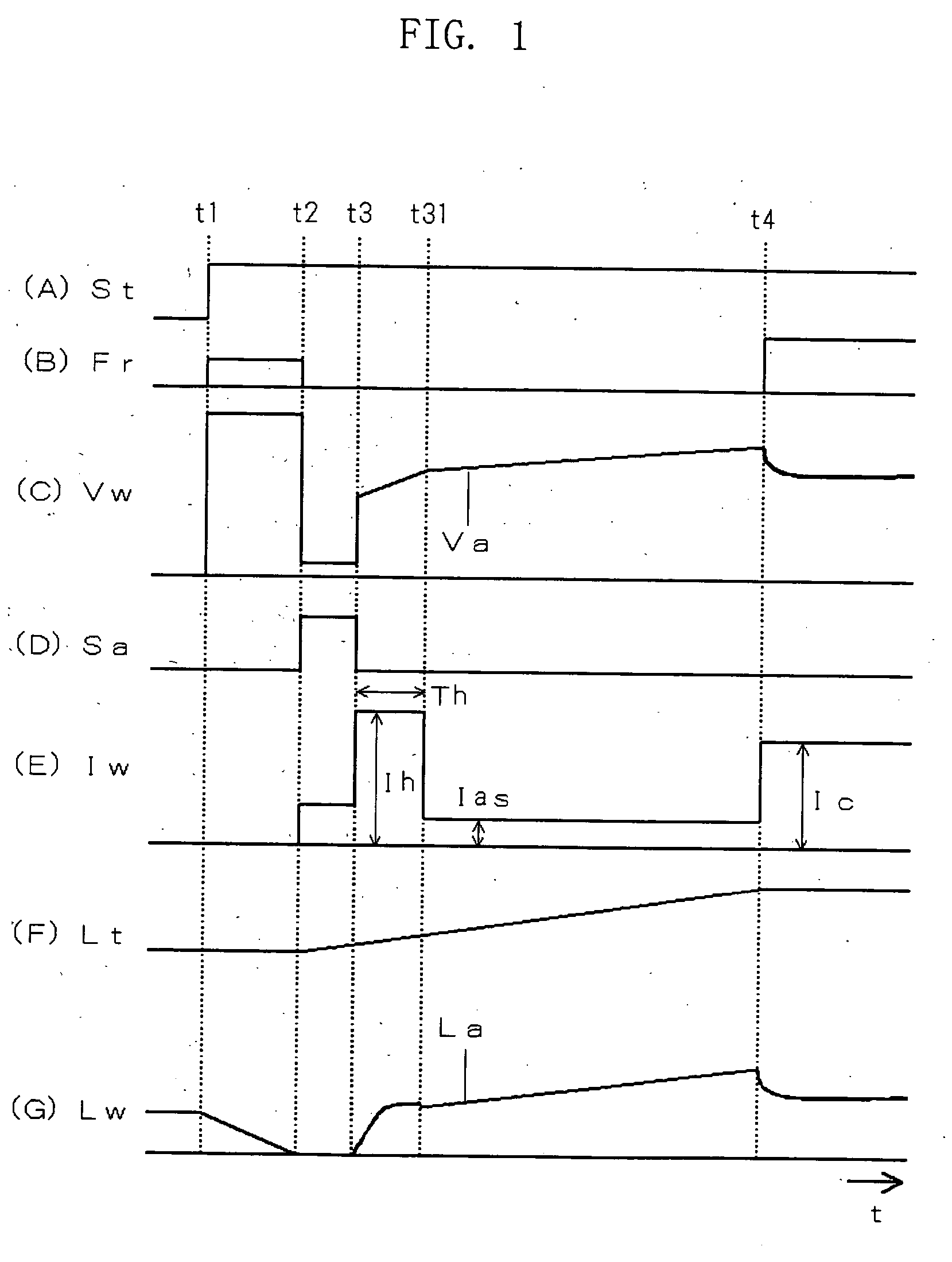
[0033]FIG. 2 is a timing chart of an arc start control method in robot welding according to Embodiment 2 of the present invention. This figure corresponds to the above-described FIG. 1, differing only in variable control of the re-shorting prevention period Th. Hereinafter, the difference will be described with reference to FIG. 2.

[0034] The re-shorting prevention period Th begins at Time Point t3 upon generation of the initial arc, and ends at Time Point t31 when the arc length La achieves a predetermined value Lm. Specifically, the determination that the arc length La reaches a predetermined value Lm as shown by (G) is performed by checking that the voltage Va reaches a predetermined value Vm, as shown by (C), corresponding to the arc length Lm. This enables to set the arc length La to an appropriate value surely at the time when the re-shorting prevention period Th ends. Therefore, this eliminates the need for time-consuming experiments in an attempt to obtain appropriate value ...

embodiment 3

[0035]FIG. 3 is a timing chart of an arc start control method in robot welding according to Embodiment 3 of the present invention. This figure corresponds to the above-described FIG. 1, differing only in variable control of the re-shorting prevention current Ih. Hereinafter, the difference will be described with reference to FIG. 3.

[0036] The re-shorting prevention current Ih is controlled so as to be substantially in inverse proportion to the change in arc voltage Va shown by (C) in the figure. Specifically, in accordance with a function Ih=f(Va), the re-shorting prevention current Ih is varied as a function of the arc voltage Va. When the arc voltage Va increases, the re-shorting prevention current Ih decreases in an inverse relationship. An example of the function is Ih=Ih0-70·(Va−Vr), where the initial value Ih0≅Ic, and Vr represents the welding voltage set value. According to this function, when the arc voltage Va increases by 1 V, the re-shorting prevention current Ih decreas...


PUM

PropertyMeasurementUnit
currentaaaaaaaaaa
arc lengthaaaaaaaaaa
current Ihaaaaaaaaaa

Abstract

An arc start control method in robot welding includes the steps of shorting a welding wire with a base metal, retracting a welding torch by a welding robot for taking the welding wire off the base metal to generate an initial arc, retracting the welding torch to a predetermined position with maintaining the initial arc maintained while applying an initial arc current smaller than a steady welding current during this initial arc period, and starting to feed the welding wire steadily and to supply the steady welding current so as to make a transition from the initial arc to a steady arc as well as starting to move the welding torch along a welding line. During a re-shorting prevention period which starts from a beginning of the initial arc period, a re-shorting prevention current which is larger than the initial arc current is applied in order to prevent re-shortening between the wire tip and the base metal right after the initial arc was generated. Thereafter, the initial arc current is applied.

Description

BACKGROUND OF THE INVENTION [0001] 1. Field of the Invention [0002] The present invention relates to an arc start control method in robot welding for improved arc start in the retract arc starting in which the welding wire is first shorted with the base metal and then the welding torch is retracted by the welding robot to move the welding wire off the base metal to generate an arc. [0003] 2. Description of the Related Art [0004]FIG. 5 is a configuration diagram of a robot welder which performs consumable electrode arc welding. A robot controller RC outputs an operation control signal Mc for controlling operation of a multi-axis servo motor disposed in a robot main body (manipulator) RM, as well as sending and receiving interface signals which include a welding start signal St, a feeding rate setting signal Fr, a welding voltage setting signal Vr and a short / arc determination signal Sa, to and from a welding power source PS. The welding power source PS, which receives and sends the i...

Claims


Application Information

Patent Timeline
Patent Type & Authority Applications(United States)
IPC IPC(8): B23K9/06
CPCB23K9/0671
Inventor UEZONO, TOSHIROERA, TETSUOUEYAMA, TOMOYUKIHIROTA, SHUGO
Owner DAIHEN CORP
Why Eureka
Try Eureka