LCD television

a technology of lcd television and stand, which is applied in the field of lcd television, can solve the problems of inability to stand upright with the rear case removed, inability to detach the stand, and inability to stand upright with the back cover removed, so as to reduce the manufacturing cost

Active Publication Date: 2007-03-01
FUNAI ELECTRIC CO LTD
View PDF3 Cites 10 Cited by
  • Summary
  • Abstract
  • Description
  • Claims
  • Application Information

AI Technical Summary

Problems solved by technology

The LCD television disclosed in Japanese Patent Laid-open Publication (JP-A) No. 15542 / 2003 requires that the stand be detached to remove the rear case, making it impossible to stand the LCD television upright with the rear case removed.
With the plasma display apparatus disclosed in JP-A No. 126456 / 2004, it is necessary to detach the stand unit to remove the back cover, making it impossible to stand the plasma display apparatus upright with the back cover removed.
This results in the following problems:
(A) It is impossible to detach the stand by removing the fixing screws with the LCD display unit standing upright.
(B) Since many, four or more, fixing screw are required to fix together the support bracket and mounting bracket, material cost becomes high in manufacturing the LCD display unit, and also assembling the support bracket and mounting bracket requires much labor, resulting in high manufacturing cost of the LCD display unit.
(C) Since the support bracket is guided by the guide rails, a slight deformation of the support bracket or mounting bracket may increase friction resistance excessively, making it impossible to insert the support bracket in the mounting bracket.
In this art, since a connector projects downward from the lower surface of a display unit, a good appearance may not be obtained when the display unit is hung on a wall, and also the display unit does not stand upright by itself.

Method used


Image

  • LCD television
  • LCD television
  • LCD television

Examples


Embodiment Construction

[0053] The detailed description set forth below in connection with the appended drawings is intended as a description of presently preferred embodiments of the invention and is not intended to represent the only forms in which the present invention may be constructed and or utilized.

[0054] The embodiments of the present invention are described below in the following order:

[0055] (1) Description of an LCD television

[0056] (2) Advantages of the LCD television

[0057] (3) Modifications

[0058] (1) Description of an LCD Television:

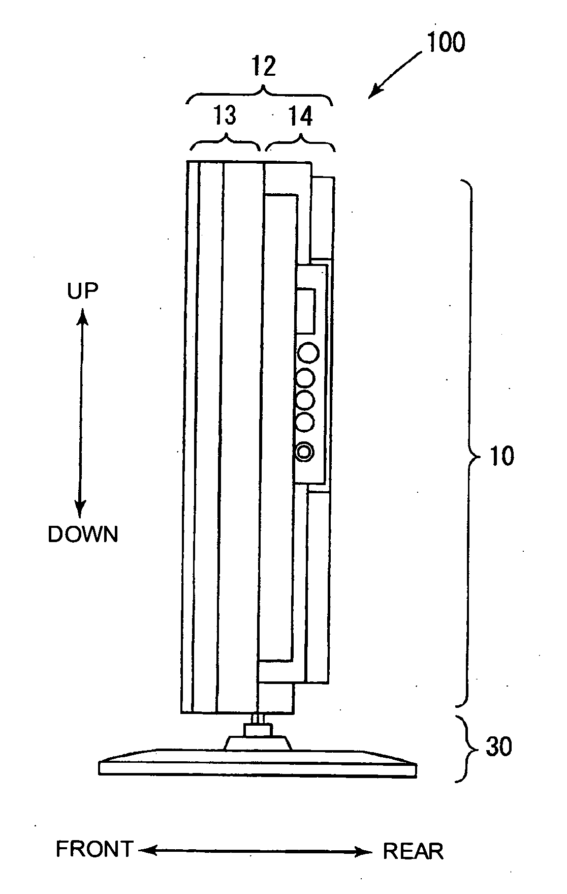
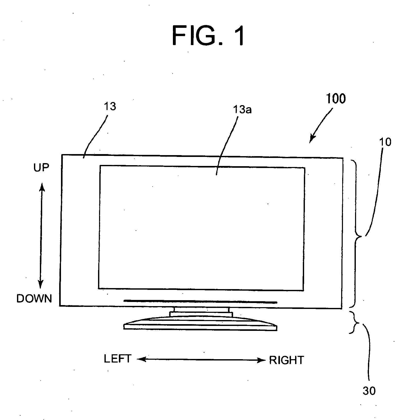
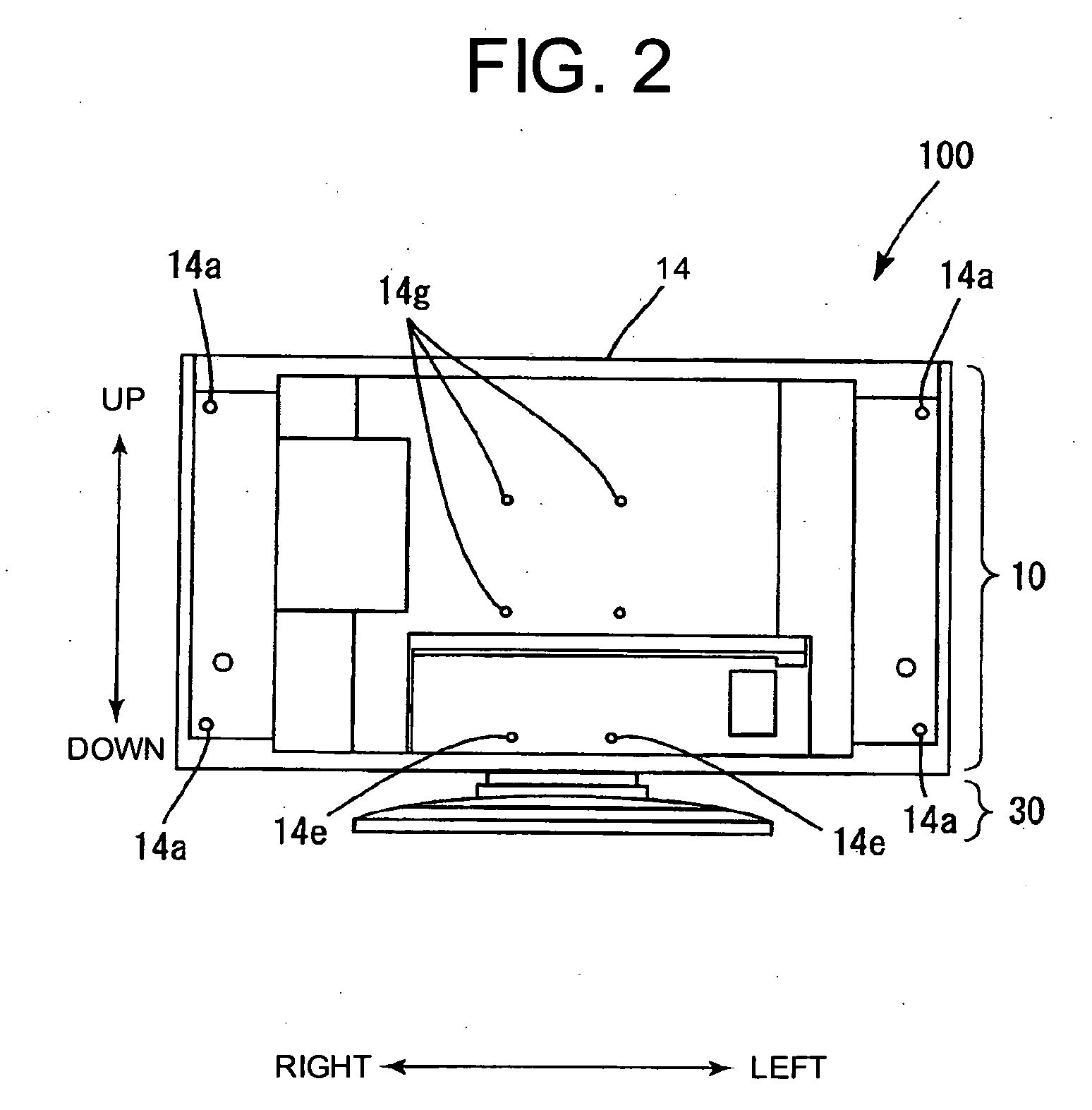
[0059]FIG. 1 is a front view of an LCD television (hereinafter referred to as TV) 100 according to an embodiment of the present invention, FIG. 2 is a rear view of the TV, FIG. 3 is a right side view of the TV, FIG. 4 is a bottom view of a body 10 of the TV, FIGS. 5 through 7 are views illustrating how to assemble the TV, seen from the rear side of the TV, FIG. 8 is a partially perspective right side view of a stand 30 illustrating its substantial part, a ti...


PUM


Abstract

The present invention is intended to enable a body of an LCD television to stand upright even when a rear cabinet is removed, to enable the body alone to be used as a wall-hanging television without removing the rear cabinet, and to eliminate or reduce the screws for fixing a support bracket to a body-side bracket. The body-side bracket comprises a lower holding portion that causes both horizontal edges of the support bracket to be inserted upward and retains the support bracket slidably, an upper holding portion that causes an upper edge of the support bracket to be inserted upward and retains the support bracket slidably, and a stopper portion to constrain upward movements of the support bracket inserted in a bracket insertion slot from underneath and slides the support bracket upward to insert in the upper holding portion for fixing.

Description

CROSS-REFERENCES TO RELATED APPLICATIONS [0001] The present application is related to the Japanese Utility Model Application No. 2005-6952, filed Aug. 25, 2005, the entire disclosure of which is expressly incorporated by reference herein. BACKGROUND OF THE INVENTION [0002] (1) Field of the Invention [0003] The present invention relates to an LCD television having a stand that supports the body of the LCD television from underneath via a body-side bracket, by extending a support bracket fixed to the body-side bracket. [0004] (2) Description of Related Art [0005] The LCD television disclosed in Japanese Patent Laid-open Publication (JP-A) No. 15542 / 2003 requires that the stand be detached to remove the rear case, making it impossible to stand the LCD television upright with the rear case removed. [0006] With the plasma display apparatus disclosed in JP-A No. 126456 / 2004, it is necessary to detach the stand unit to remove the back cover, making it impossible to stand the plasma display...

Claims


Application Information

Patent Timeline
Patent Type & Authority Applications(United States)
IPC IPC(8): H04N5/64
CPCF16M11/00F16M11/10H04N5/64F16M2200/08F16M11/22H04N5/655
Inventor YOKAWA, AKIRA
Owner FUNAI ELECTRIC CO LTD
Why Eureka
Try Eureka