Radiological imaging system

a radiation imaging and radiation technology, applied in the field of radiation imaging systems, can solve the problems of low detection rate of -rays, poor picture quality in ordinary cases, and inability to understand the positional relationship of surrounding organs, so as to improve energy resolution, less intimidating, accurate diagnosis

Inactive Publication Date: 2007-03-15
UENO YUUICHIROU +7
View PDF22 Cites 15 Cited by
  • Summary
  • Abstract
  • Description
  • Claims
  • Application Information

AI Technical Summary

Benefits of technology

[0013] In order to solve the problem, in a first invention, semiconductor radiation detectors are used for a first imaging apparatus (PET imaging apparatus) to increase detection accuracy. In this configuration, the semiconductor radiation detectors are used to directly detect a radiation, thereby improving a position resolution and an energy resolution. Further, since an energy resolution can be improved, internal scattering is removed (noise is reduced). Therefore, it is possible to improve quantitativeness in 3D imaging and eliminate the need for the septa for 2D imaging, thereby miniaturizing the apparatus. Further, detection elements can be smaller in size, achieving a radiological imaging system which is entirely miniaturized.
[0014] Besides, since absorption correction can be performed using a second imaging apparatus (X-ray CT imaging apparatus), it is not necessary to provide an absorption correction source (γ-ray, etc.) in the first imaging apparatus, thereby further miniaturizing the apparatus.
[0016] In a third invention, the first imaging apparatus (PET imaging apparatus) is formed with a smaller size than the second imaging apparatus (X-ray CT imaging apparatus), and the first imaging apparatus is disposed in front of the second imaging apparatus. Thus, the overall apparatus becomes less intimidating to an examinee.
[0017] The present invention makes it possible to improve an energy resolution and achieve an accurate diagnosis.

Problems solved by technology

On the other hand, since SPECT uses a collimator, the detection rate of γ-rays is low and picture quality is poor in ordinary cases.
Thus, although a part where chemicals accumulate can be extracted with high contrast, the positional relationship of surrounding organs cannot be understood.
Thus, it is not always possible to conduct an accurate diagnosis.
Particularly a quantitative evaluation cannot be made in 3D imaging of PET due to a reduction in energy resolution.
This is because a γ-ray energy threshold value has to be reduced due to a low energy resolution and internal scattering, which is noise increased in 3D imaging, is frequently detected.
Moreover, in the case of a radiological imaging system having a conventional serial arrangement of X-ray CT, PET, SPECT, etc., the overall apparatus is prone to increase in size, thereby intimidating an examinee.

Method used


Image

  • Radiological imaging system
  • Radiological imaging system
  • Radiological imaging system

Examples


embodiment 1

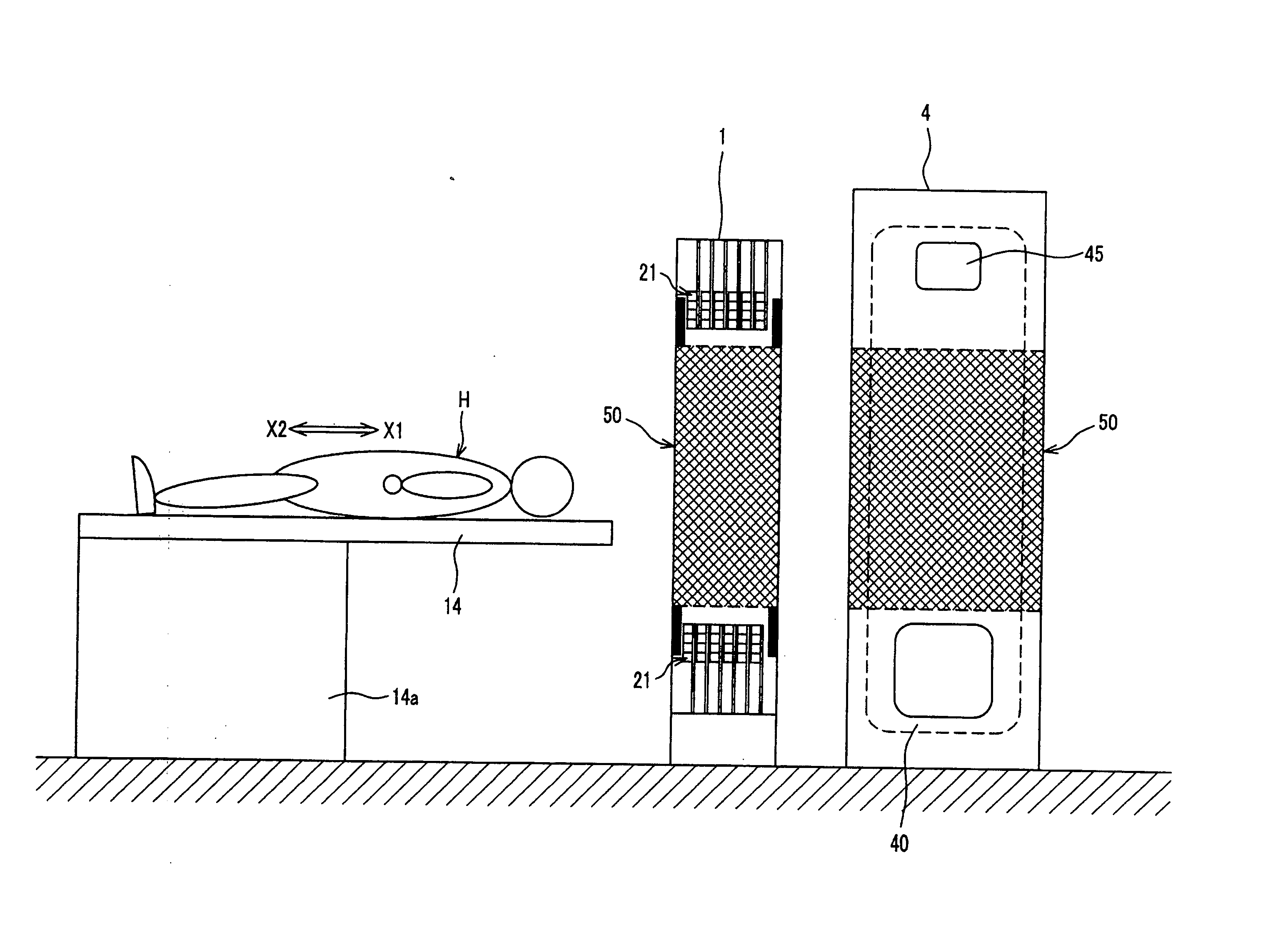
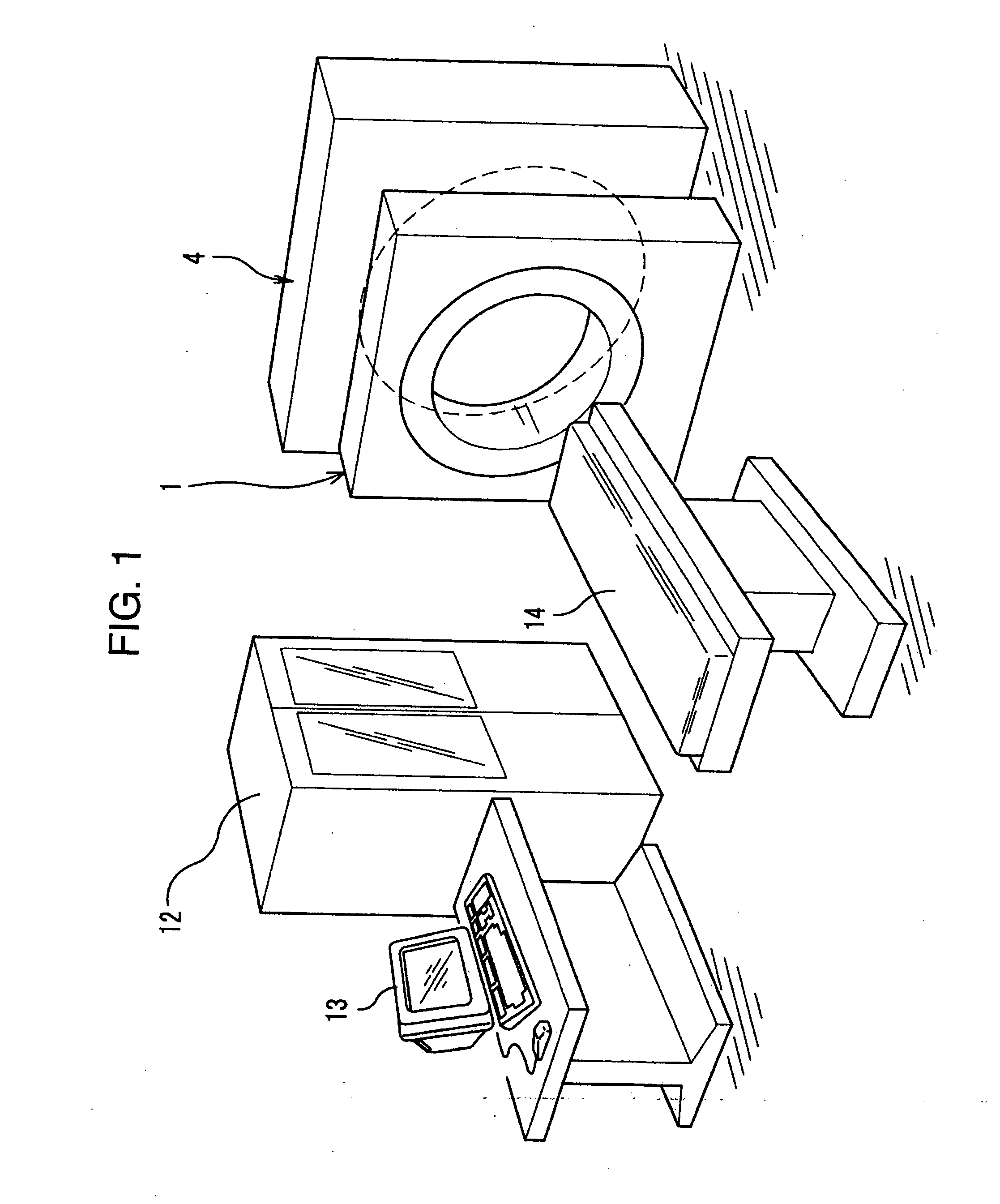
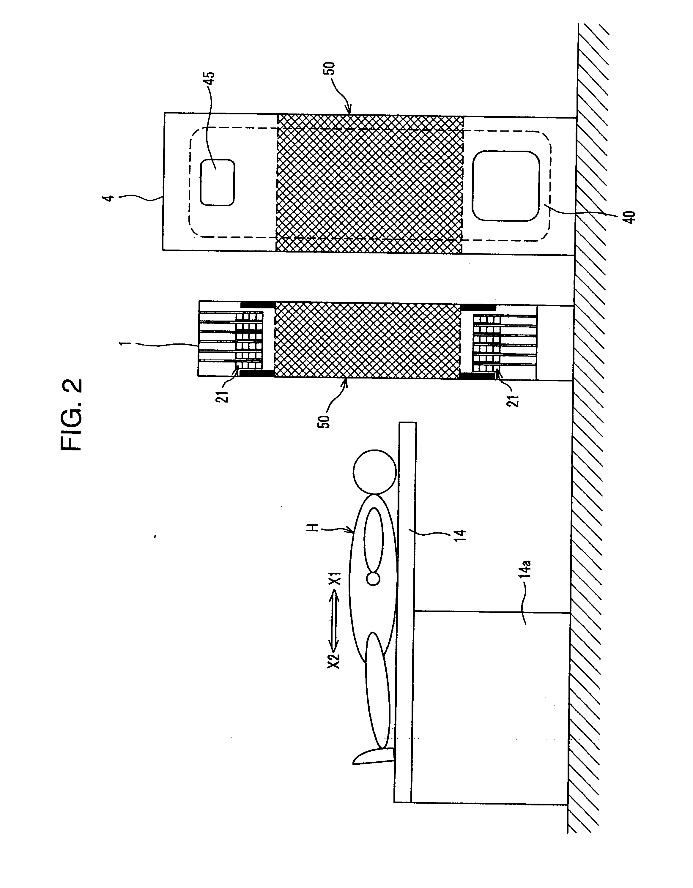
[0046] As shown in FIGS. 1 and 2, the radiological imaging system of the present embodiment has two independent gantries which comprise a bed 14 serving as a berthing apparatus, a PET imaging apparatus 1 serving as a first imaging apparatus, and an X-ray CT imaging apparatus 4 serving as a second imaging apparatus. As shown in FIG. 1, the radiological imaging system includes a data processing apparatus 12 and a display apparatus 13. An examinee (subject) H is loaded on the bed 14 which can move forward and backward along the body axis direction (X1 and X2 directions) of the examinee H, and the examinee H is imaged by the PET imaging apparatus 1 and the X-ray CT imaging apparatus 4.

A. (PET Imaging Apparatus)

[0047] The PET imaging apparatus 1 includes a number of semiconductor radiation detectors 21 (FIGS. 4, 8, 11). γ-rays radiated from the inside of the examinee H are detected by the semiconductor radiation detectors (hereinafter, simply referred to as detectors) 21. The PET imag...

embodiment 2

[0143] A radiological imaging system of another embodiment will be described below. As shown in FIG. 18, the present embodiment is different from Embodiment 1 in that semiconductor radiation detectors 21 are used as a radiation detector in an X-ray CT imaging apparatus 4. To be specific, a plurality of combined substrates 60 shown in FIGS. 19A, 19B are provided in a slicing direction (four slices in the present embodiment) via a detector holding part 46, and the combined substrates 60 rotates around an examinee H in synchronization with an X-ray source circumferential moving apparatus 41. As with the combined substrate 20 of Embodiment 1, the combined substrate 60 has detectors 21, resistors 23, analog ASICs 24A, ADCs 25, and a digital ASIC 26A. This configuration is similar to that of Embodiment 1 except for a smaller number of detectors 21, the analog ASIC 24, and the ADC 25. That is, 16 detectors 21 are provided in one line and thus 32 detectors 21 are provided on both sides one ...


PUM


Abstract

The radiological imaging system which can improve an energy resolution and perform a diagnosis with high accuracy includes a bed for carrying an examinee H, first and second imaging apparatuses and disposed along the longitudinal direction of the bed. The first imaging apparatus has a plurality of semiconductor radiation detectors for detecting γ-rays emitted from the examinee H, arranged around the bed, the second imaging apparatus has an X-ray source for emitting X-rays to the examinee H and a radiation detector for detecting X-rays which have been emitted from the X-ray source and passed through the examinee H, and the bed is shared by the first imaging apparatus and the second imaging apparatus.

Description

CROSS-REFERENCE TO RELATED APPLICATION [0001] The present application is related to a U.S. Ser. No. ______ being filed based on Japanese Patent Application No. 2003-340688 filed on Sep. 30, 2003, the entire content of which is incorporated herein by reference. BACKGROUND OF THE INVENTION [0002] The present invention relates to a radiological imaging system using a radiation and particularly relates to a radiological imaging system suitable for carrying out two or more kinds of radiological examinations including an X-ray CT examination and a positron emission computed tomography (hereinafter referred to as “PET”) examination. [0003] Examination techniques using radiations realize nondestructive examinations in the body of an examinee. Particularly radiological examination techniques for a human body include X-ray CT, PET, single photon emission computed tomography (hereinafter referred to as “SPECT”). [0004] In all of these techniques, a physical quantity to be examined is measured ...

Claims


Application Information

Patent Timeline
Patent Type & Authority Applications(United States)
IPC IPC(8): G01T1/164G01T1/24H01L27/146H01L25/00A61B6/03G01T1/161G01T1/29H01L27/14H01L31/09H04N5/32
CPCA61B6/032A61B6/037G01T1/1611G01T1/1614G01T1/243G01T1/2985H01L31/1085H01L31/119G01T1/249
Inventor UENO, YUUICHIROUKITAGUCHI, HIROSHITSUCHIYA, KATSUTOSHIAMEMIYA, KENSUKEYOKOI, KAZUMAKOJIMA, SHINICHIYANAGITA, NORIHITOISHITSU, TAKAFUMI
Owner UENO YUUICHIROU
Why Eureka
Try Eureka