Power control apparatus, electrically powered vehicle and power control method of power system

a power control apparatus and power system technology, applied in the direction of motor/generator/converter stopper, multiple dynamo-motor starters, electric devices, etc., can solve the problems of excessive power waste, surplus power cannot be used up in sufficient quantities, and power consumption is not controlled successively

Active Publication Date: 2007-03-29
TOYOTA JIDOSHA KK
View PDF19 Cites 22 Cited by
  • Summary
  • Abstract
  • Description
  • Claims
  • Application Information

AI Technical Summary

Benefits of technology

[0026] Therefore, in accordance with the electrically powered vehicle of the present invention, the amount of power consumption by the electric load can be controlled successively, in accordance with the surplus power generated at the time of regenerative braking. As a result, the generated surplus power can be consumed neither too much nor too little by the electric load.

Problems solved by technology

The regenerative braking apparatus disclosed in Japanese Patent Laying-Open No. 2004-254465, however, simply combines electric loads in accordance with the magnitude of surplus power, and it is impossible to successively control the amount of power consumption by the surplus power consuming loads in accordance with the magnitude of the surplus power.
Therefore, it is still possible that the surplus power cannot sufficiently be used up, or excessive power might be wasted.

Method used


Image

  • Power control apparatus, electrically powered vehicle and power control method of power system
  • Power control apparatus, electrically powered vehicle and power control method of power system
  • Power control apparatus, electrically powered vehicle and power control method of power system

Examples


Embodiment Construction

[0034] In the following, an embodiment of the present invention will be described in detail with reference to the figures. Throughout the figures, the same or corresponding portions are denoted by the same reference characters and description thereof will not be repeated.

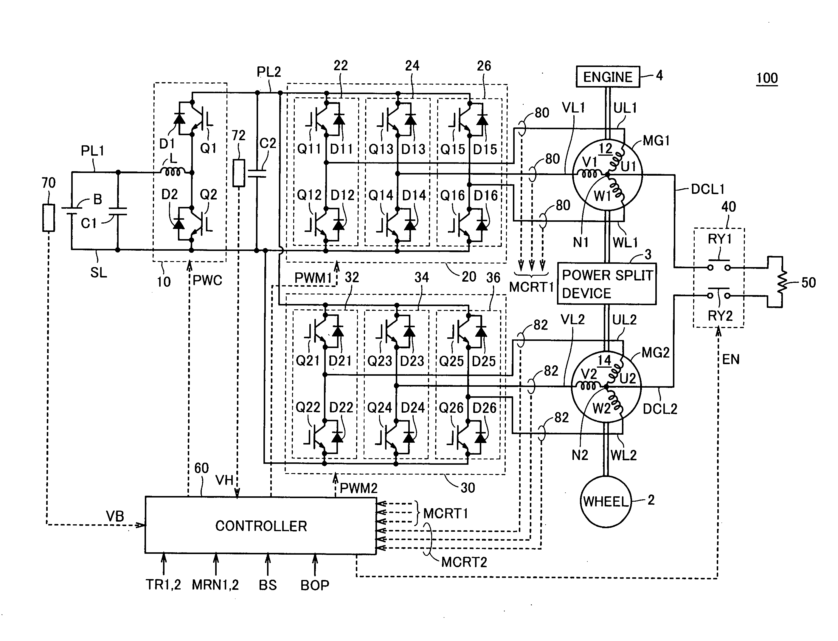
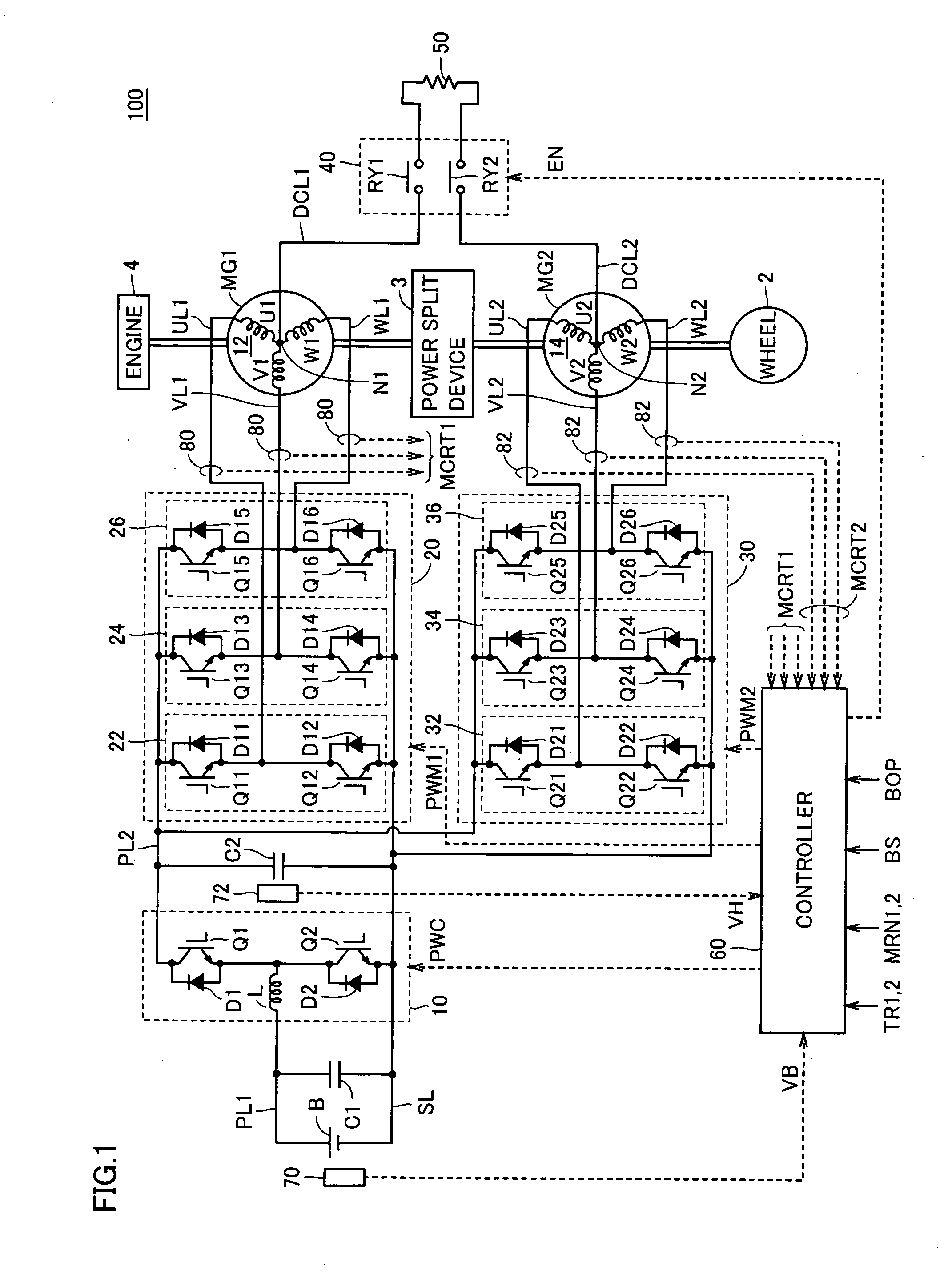
[0035]FIG. 1 is an overall block diagram of a hybrid vehicle 100 shown as an example of the electrically powered vehicle in accordance with an embodiment of the present invention. Referring to FIG. 1, a hybrid vehicle 100 includes an engine 4, motor generators MG1 and MG2, a power split device 3 and wheels 2. Further, hybrid vehicle 100 includes an electric storage B, a boost converter 10, inverters 20 and 30, a controller 60, capacitors C1 and C2, power lines PL1 and PL2, a ground line SL, U-phase lines UL1 and UL2, V-phase lines VL1 and VL2, W-phase lines WL and WL2, voltage sensors 70 and 72, and current sensors 80 and 82. Hybrid vehicle 100 further includes power lines DCL1 and DCL2, a relay circuit 40 and a re...


PUM


Abstract

When surplus power not charged to an electric storage is generated at the time of regenerative braking of a vehicle, a voltage is generated across first and second neutral points using a zero-voltage vector each of first and second inverters and the generated surplus power is consumed by a resistance connected across the first and second neutral points. The voltage generated across the first and second neutral points is calculated in accordance with the surplus voltage, using a resistance value of the resistance.

Description

[0001] This nonprovisional application is based on Japanese Patent Application No. 2005-285043 filed with the Japan Patent Office on Sep. 29, 2005, the entire contents of which are hereby incorporated by reference. BACKGROUND OF THE INVENTION [0002] 1. Field of the Invention [0003] The present invention relates to a power control apparatus and an electrically powered vehicle, and more specifically to power control at the time of regenerative braking of an electrically powered vehicle. [0004] 2. Description of the Background Art [0005] In an electrically powered vehicle such as an electric vehicle or a hybrid vehicle that runs using a motor as a power source, at the time of braking of the vehicle, regenerative braking is generally done, in which the motor is rotated by the rotating force from the driving wheel to regenerate power, and the braking force corresponding to the regenerated power is used as the braking force of the vehicle. [0006] When the vehicle is running on a long, dow...

Claims


Application Information

Patent Timeline
Patent Type & Authority Applications(United States)
IPC IPC(8): H02P3/14B60K6/442B60K6/445B60L7/16B60W10/08B60W10/18B60W10/26B60W20/00H02P3/18H02P27/06
CPCB60L7/22Y02T10/7077B60L11/14B60L15/025B60L2220/14B60L2220/54B60W10/08B60W10/26B60W10/30B60W20/00B60W30/18127B60W2510/18Y02T10/6217Y02T10/641Y02T10/643B60L11/123B60L50/61B60L50/16Y02T10/62Y02T10/64Y02T10/7072Y02T10/70B60W20/13
Inventor OYOBE, HICHIROSAISASAKI, SHOICHINAKAMURA, MAKOTOISHIKAWA, TETSUHIRO
Owner TOYOTA JIDOSHA KK
Why Eureka
Try Eureka