Fuel cell system and control method of the same

a fuel cell and control method technology, applied in the direction of battery/fuel cell control arrangement, cell components, electrochemical generators, etc., can solve the problems of large amount of heat generated, inability to obtain sufficient durability, etc., to prevent cross leakage and prevent deterioration of fuel economy

Inactive Publication Date: 2007-01-02
TOYOTA JIDOSHA KK
View PDF7 Cites 10 Cited by
  • Summary
  • Abstract
  • Description
  • Claims
  • Application Information

AI Technical Summary

Benefits of technology

[0009]The invention is made in consideration of the above-described problem. It is an object of the invention to provide a fuel cell system in which cross leak can be prevented when an output terminal of a stack is disconnected from a load, and a control method thereof. Also, it is another object of the invention to provide a fuel cell system in which deterioration of fuel economy can be prevented when cross leak is prevented, and a control method thereof.
[0011]In a fuel cell system with such a configuration, when the output terminal of the fuel cell stack is disconnected from the load, the hydrogen in each of the unit cells is consumed by short-circuiting the positive electrode and the negative electrode of the output terminal of the stack after distribution of the fuel gas to the fuel gas passage is prohibited in the fuel gas supply manifold. Accordingly, cross leak of hydrogen can be prevented. Also, distribution of the fuel gas is stopped in the fuel gas supply manifold, unlike a conventional method in which the supply of the fuel gas is stopped in gas piping which is provided outside the stack. Accordingly, the amount of the hydrogen which remains after distribution of the fuel gas is stopped is smaller, the amount of the hydrogen which is consumed when the positive electrode and the negative electrode of the output terminal are short-circuited is smaller, and the amount of heat generation is smaller, as compared with the conventional method. Accordingly, deterioration of durability due to heat generated at the time of short-circuit can be suppressed, and unnecessary consumption of large amount of hydrogen can be avoided. Therefore, according to this fuel cell system, cross leak can be prevented when the output terminal of the stack is disconnected from the load, and deterioration of fuel economy can be avoided.
[0015]According to the method, when the output terminal of the fuel cell stack is disconnected from the load, the hydrogen in each of the unit cells is consumed by short-circuiting the positive electrode and the negative electrode of the output terminal of the stack after distribution of the fuel gas to the fuel gas passage of each of the unit cells is prohibited in the fuel gas supply manifold. Accordingly, cross leak of the hydrogen can be prevented. Also, distribution of the fuel gas is stopped in the fuel gas supply manifold, unlike the conventional method in which the supply of the fuel gas is stopped in gas piping which is provided outside the stack. Accordingly, the amount of the hydrogen which remains after distribution of the fuel gas is stopped is smaller, the amount of the hydrogen which is consumed when the positive electrode and the negative electrode of the output terminal are short-circuited is smaller, and an amount of heat generation is smaller, as compared with the conventional method. Accordingly, deterioration of durability due to heat generated at the time of short-circuit can be suppressed, and unnecessary consumption of large amount of hydrogen can be avoided. Therefore, according to the control method of the fuel cell, cross can be prevented when the output terminal of the stack is disconnected from the load, and deterioration of fuel economy can be avoided.

Problems solved by technology

As a result, there is a possibility that sufficient durability cannot be obtained due to the cross leak of the hydrogen gas.
For example, when the amount of the cross-leaked hydrogen gas is large, hydrogen directly reacts with oxygen on the cathode side, which generates a large amount of heat, and the electrolyte membrane is damaged due to the heat.
As a result, there is a possibility that sufficient durability cannot be obtained.
Also, since interruption of the supply of the fuel gas is configured to be performed by a valve or the like which is provided in the gas piping, a considerable amount of the fuel gas remains in the gas piping and the manifold after the supply of the gas is interrupted.
When the positive electrode and the negative electrode of the output terminal are short-circuited in this state, a large amount of heat is generated.
Accordingly, there still exists a problem concerning durability.
Also, there is another problem that it becomes difficult to obtain good fuel economy, which is supposed to be obtained, since a large amount of fuel gas is unnecessarily consumed.

Method used


Image

  • Fuel cell system and control method of the same
  • Fuel cell system and control method of the same
  • Fuel cell system and control method of the same

Examples


Embodiment Construction

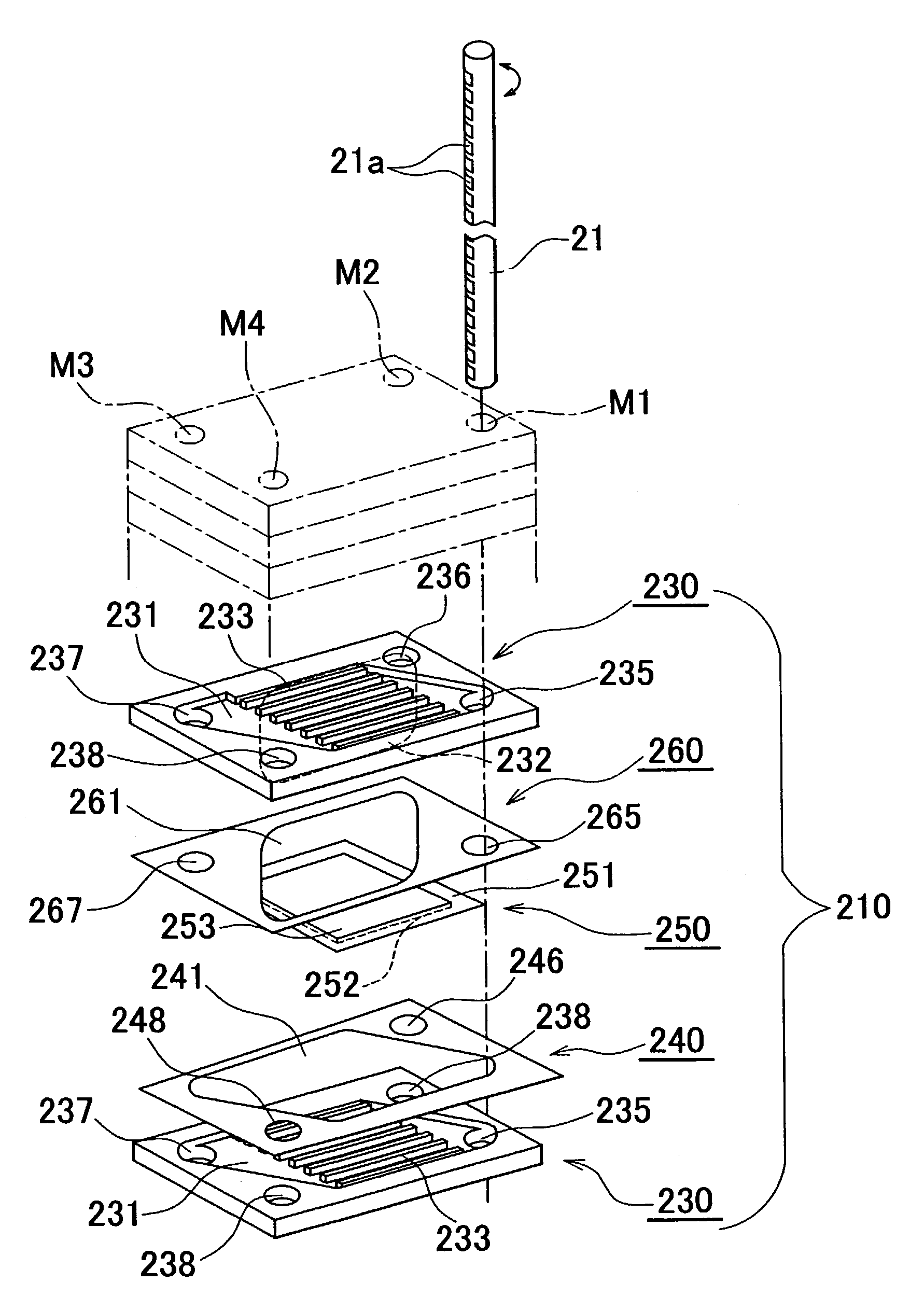
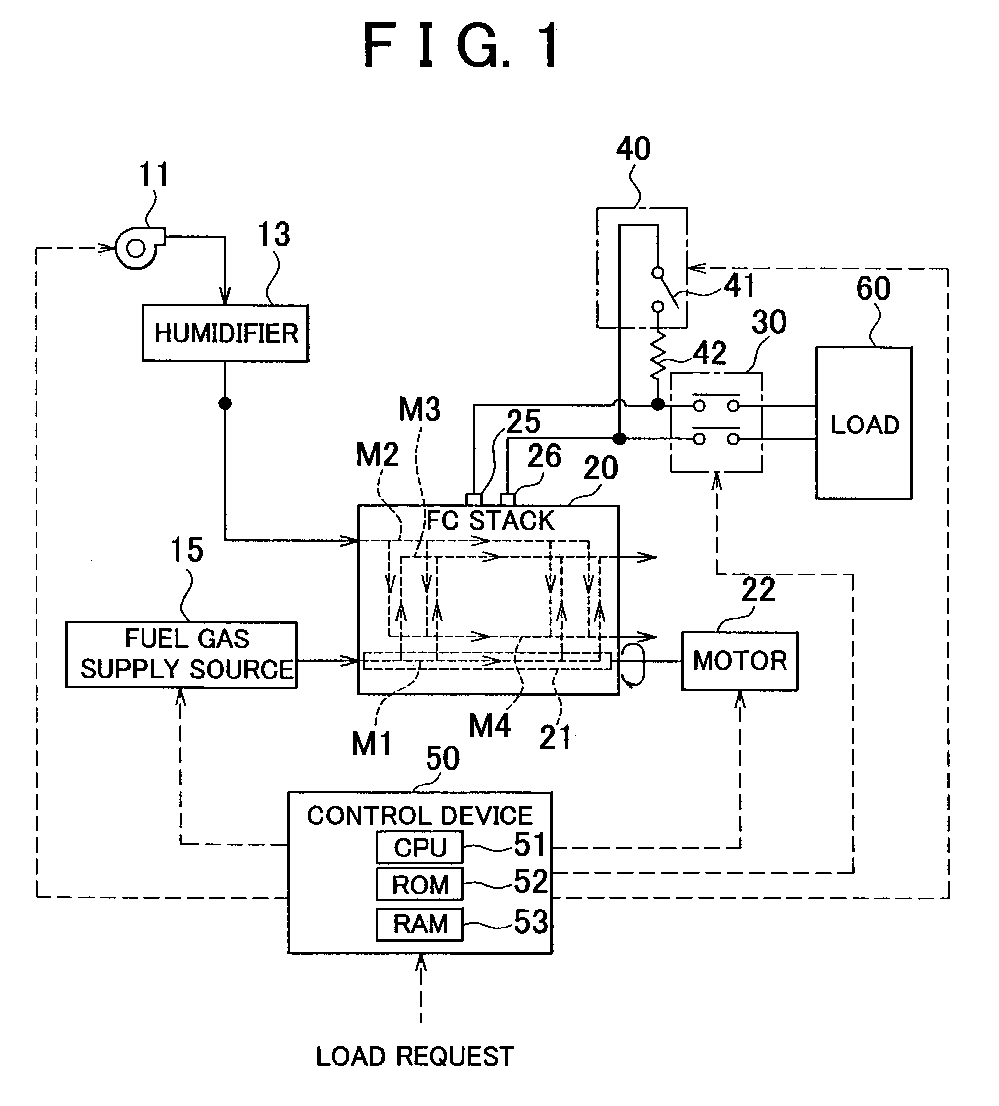
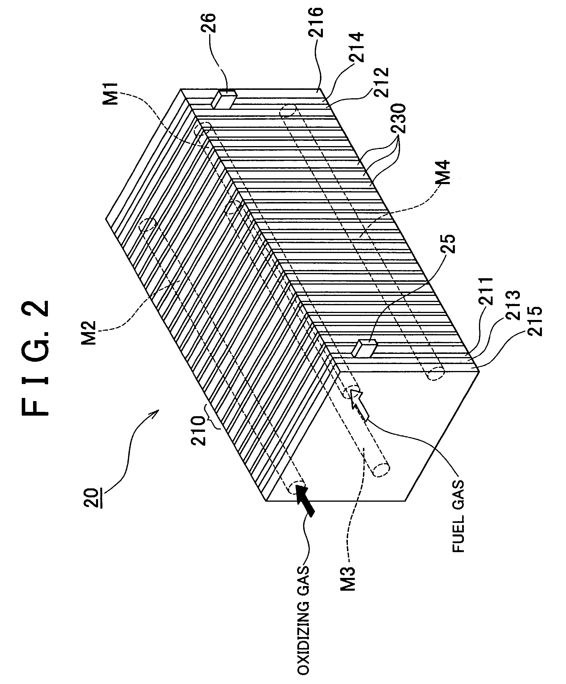
[0023]In order to further clarify the invention, hereafter, an exemplary embodiment of the invention will be described with reference to accompanying drawings. FIG. 1 is a block diagram schematically showing a fuel cell system 10 according to the embodiment, FIG. 2 is a perspective view of an FC stack 20, and FIG. 3 is an exploded perspective view of a unit cell 210.

[0024]The fuel cell system 10 according to the embodiment mainly includes a fuel cell stack (hereinafter, referred to as an FC stack) 20 of a solid polyelectrolyte type, a first interrupter 30 which is provided between output terminals 25, 26 of the FC stack 20 and a load 60, a second interrupter 40 which is provided between the output terminals 25, 26 of the FC stack 20, and a control device 50 which controls a supply of fuel gas and oxidizing gas to the FC stack 20 and controls connection and disconnection by the first interrupter 30 and the second interrupter 40.

[0025]The FC stack 20, which will be described later in ...


PUM

PropertyMeasurementUnit
proton conductivityaaaaaaaaaa
durabilityaaaaaaaaaa
heataaaaaaaaaa

Abstract

A fuel cell system in which fuel gas and oxidizing gas are supplied to a fuel cell stack and power generation is performed by electrochemical reaction between the fuel gas and the oxidizing gas, and a control method thereof are provided. This fuel cell system includes a fuel gas supply manifold which is extended in a unit cell stacking direction and which distributes the fuel gas to a fuel gas passage; a switching device which is provided inside the fuel gas supply manifold, and which switches between permission and prohibition of distribution of the fuel gas to the fuel gas passage of each of the unit cells; a load disconnect device which disconnects an output terminal of the stack from a load; a short-circuit device which short-circuits a positive electrode and a negative electrode of the output terminal of the stack; and a control device which short-circuits the positive electrode and the negative electrode of the output terminal by the short-circuit device after distribution of the fuel gas to the fuel gas passage of each of the unit cells is prohibited by the switching device when the output terminal is disconnected from the load by the load disconnect device.

Description

INCORPORATION BY REFERENCE[0001]The disclosure of Japanese Patent Application No. 2002-116950 filed on Apr. 19, 2002, including the specification, drawings and abstract is incorporated herein by reference in its entirety.BACKGROUND OF THE INVENTION[0002]1. Field of the Invention[0003]The invention relates to a fuel cell system and a control method thereof.[0004]2. Description of the Related Art[0005]A fuel cell stack is formed by stacking a plurality of unit cells. Each of the unit cells is configured such that a membrane electrode assembly (hereinafter, referred to as MEA) is sandwiched by two separators. The MEA is formed from an electrolyte membrane in which platinum as a catalytic electrode is applied to both surfaces thereof, and a pair of gas diffusion electrodes which sandwich the electrolyte membrane. The catalytic electrode and the gas diffusion electrode on one surface of the electrolyte membrane form an anode, and the catalytic electrode and the gas diffusion electrode on...

Claims


Application Information

Patent Timeline
Patent Type & Authority Patents(United States)
IPC IPC(8): H01M8/00H01M8/04H01M8/12B60L11/18H01M8/24
CPCB60L11/1885B60L11/1894H01M8/04089H01M8/04626H01M8/04835H01M8/2415H01M8/04753Y02T90/34Y02E60/50B60L58/31B60L58/34H01M8/2483Y02T90/40H01M8/2457H01M8/2484H01M8/0273
Inventor NAKANISHI, HARUYUKIMATSUMOTO, SHINICHI
Owner TOYOTA JIDOSHA KK
Why Eureka
Try Eureka