Imaging apparatus

a technology of imaging apparatus and exposure amount, which is applied in the direction of exposure control, instruments, television systems, etc., can solve the problems of unnecessarily consuming electric power in light irradiation means, difficult to appropriately adjust the exposure amount of the driver, and deteriorating the quality of the subject image taken through the obstacle. to achieve the effect of appropriate evaluation of the exposure amoun

Inactive Publication Date: 2012-12-20
PANASONIC INTELLECTUAL PROPERTY MANAGEMENT CO LTD
View PDF10 Cites 12 Cited by
  • Summary
  • Abstract
  • Description
  • Claims
  • Application Information

AI Technical Summary

Benefits of technology

[0025]With this configuration, it is possible to appropriately evaluate the exposure amount even when a subject (target object) is moving.

Problems solved by technology

As a result, quality of the subject image taken through the obstacle may be deteriorated.
Therefore, it is not easy to appropriately adjust the exposure amount of the driver (subject image) taken through the vehicle windshield.
Thus, electric power is unnecessarily consumed in the light irradiation means.
In this case, if a constant amount of light is irradiated regardless of the existence or absence of a target object in the target region, there is posed a problem in that electric power is unnecessarily consumed in the light irradiation means and the lifespan of the light irradiation means becomes shorter.
In the aforementioned conventional imaging apparatus, if a contaminant adheres to an imaging lens or a transparent cover for protection of the imaging lens or if a scratch is generated in the imaging lens or the transparent cover, there is a likelihood that the amount of light received is decreased and the quality of the differential image is reduced.
Similarly, it is likely that the amount of light received is decreased and the quality of the differential image is reduced due to the aging deterioration of a light source for irradiating light (e.g., a light emitting diode).
In the event that the imaging apparatus is used for monitoring purposes, it is difficult to perceive contamination of the lens or the cover because a monitoring camera is installed in a higher position.
The exposure amount cannot be appropriately evaluated if the evaluation range is kept fixed.

Method used


Image

  • Imaging apparatus
  • Imaging apparatus
  • Imaging apparatus

Examples


first embodiment

[0053]As shown in FIG. 1, the imaging apparatus A of the present embodiment includes a light source unit 1, a light emission control unit 2, an imaging unit 3, a drive control unit 4, a lens unit 5, an incident light amount adjusting unit 6 and an image generating unit 7. The lens unit 5 includes a plurality of infrared emission diodes arranged in a matrix pattern and irradiates infrared light on a target region (vehicle traveling road). The light emission control unit 2 supplies an electric current to the respective infrared emission diodes of the light source unit 1, thereby energizing the infrared emission diodes.

[0054]The imaging unit 3 includes an imaging element for sensing the infrared light. The drive control unit 4 drives and controls the imaging unit 3. The lens unit 5 condenses light on the imaging element of the imaging unit 3. The incident light amount adjusting unit 6 adjusts the amount of light incident on the imaging unit 3 by controlling a diaphragm of the lens unit...

second embodiment

[0094]Next, an imaging apparatus according to a second embodiment will be described with reference to FIGS. 6 through 10. Components identical with or corresponding to those of the imaging apparatus of the first embodiment will be designated by like reference symbols with no repeated description made thereon.

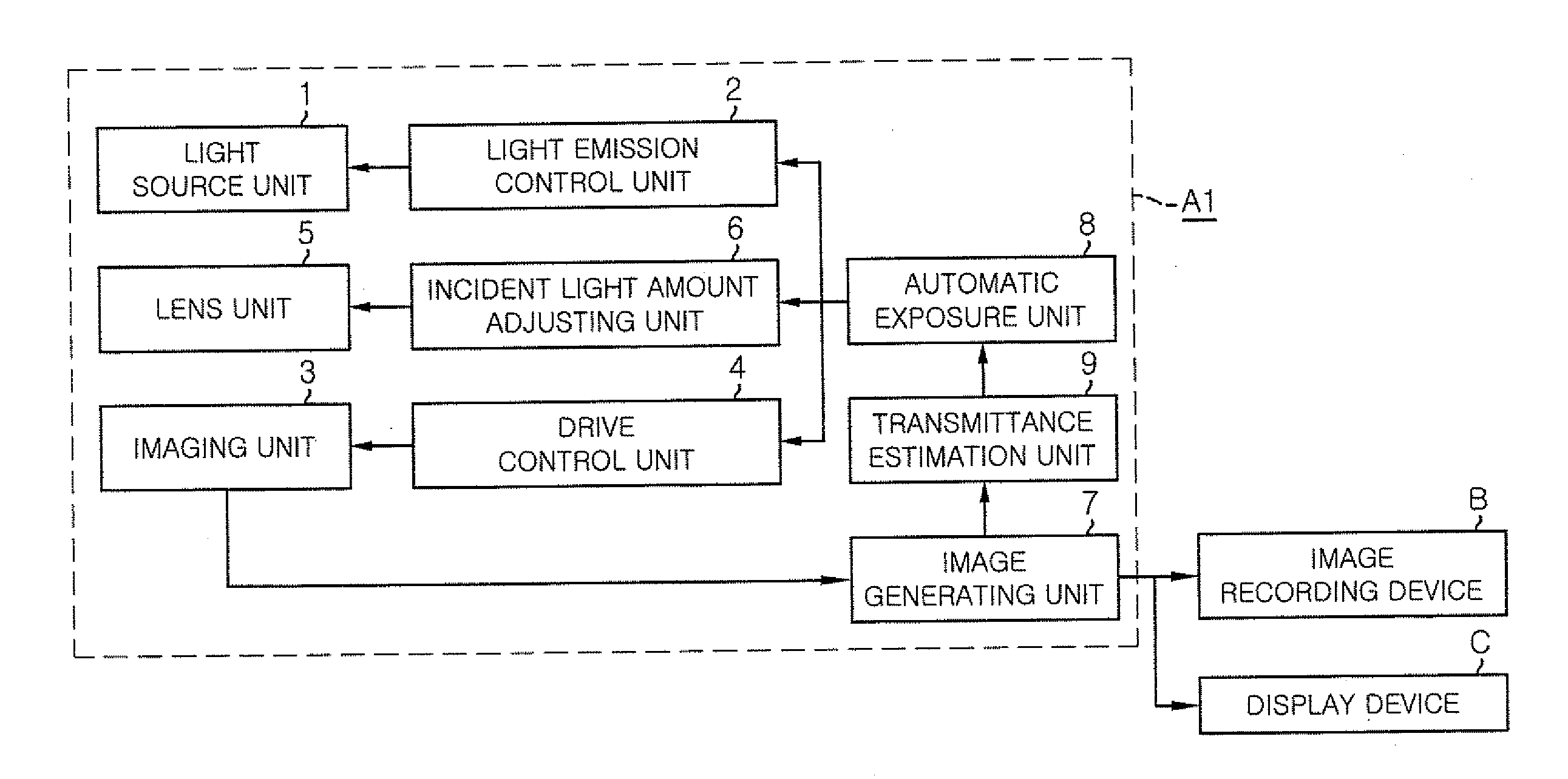
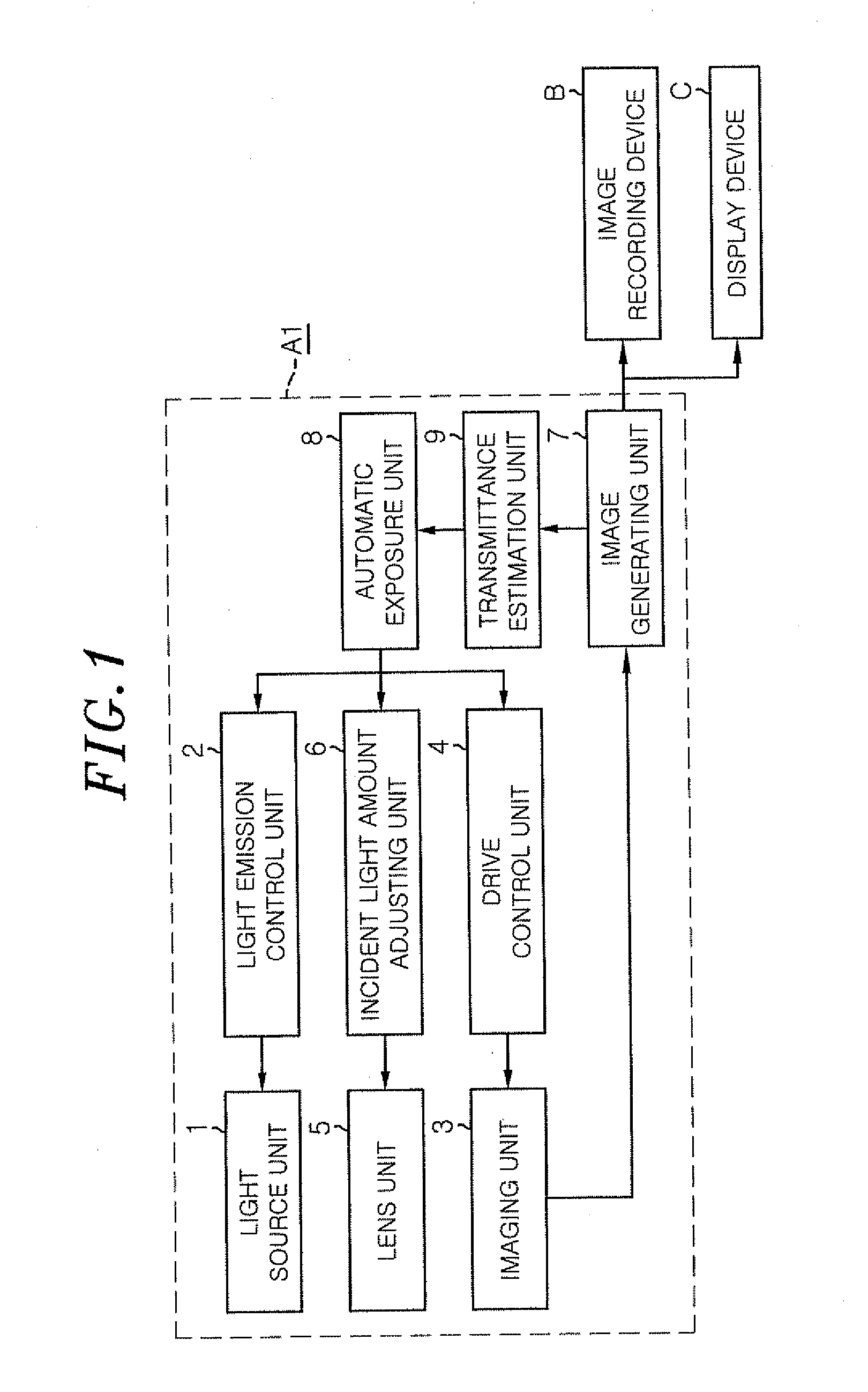
[0095]As shown in FIG. 6, the imaging apparatus A1 of the second embodiment includes a plurality of (four, in the illustrated example) light source units 1a through 1d for irradiating light (infrared light) on a target region (a vehicle traveling lane), a light emission control unit 2 for separately energizing the light source units 1a to 1d, an imaging unit 3 having an imaging element sensitive to the infrared light, and a drive control unit 4 for driving and controlling the imaging unit 3.

[0096]Further, the imaging apparatus A1 includes an image generating unit 7 for generating a differential image (light modulation image) between a first image (emission image) taken by the im...

third embodiment

[0127]Next, an imaging apparatus according to a third embodiment will be described with reference to FIGS. 11 through 14. Components identical with or similar to those of the preceding embodiments will be designated by like reference symbols with no repeated description made thereon.

[0128]As shown in FIG. 11, the imaging apparatus A6 (monitoring camera) of the present embodiment includes a light source unit 1 for energizing light sources to irradiate light on a target region, a light emission control unit 2 for supplying electric power to the light source unit 1 to energize the light sources, and an imaging unit 3 having a two-dimensional CCD image sensor (not shown) and a lens (not shown) for condensing the light on the light receiving surface of the image sensor.

[0129]Further, the imaging apparatus A6 includes an imaging control unit 4 for controlling the exposure time and exposure amount of the image sensor, an image generating unit 7 for generating a differential image between a...


PUM


Abstract

Disclosed is an imaging apparatus provided with: a light irradiation unit which irradiates a target area with light; a differential image generation unit which generates a differential image between a first image which was taken in synchronization with the irradiation period during which the light irradiation unit irradiates the light and a second image which was taken outside the irradiation period; a transmittance estimation unit which estimates the light transmittance of an object in the target area; and a light exposure adjustment unit which adjusts the exposure based on the estimation result from the transmittance estimation unit. The transmittance estimation unit estimates the transmittance of the object from at least one of the first image, the second image, and the differential image.

Description

FIELD OF THE INVENTION[0001]The present invention relates to an imaging apparatus for taking an image with a reduced influence of ambient light.BACKGROUND OF THE INVENTION[0002]The present applicant has already suggested an imaging apparatus for acquiring a differential image between an image (emission image) taken while irradiating light by a light irradiation means and an image (non-emission image) taken without irradiating light by a light irradiation means (see JP2006-121617A). In such differential image, only the reflected light components of the light irradiated from the light irradiation means are used as pixel values. This helps reduce the influence of ambient light such as sunlight or the like.[0003]In the imaging apparatus described above, if a light-transmitting obstacle such as glass (hereinafter just referred to as “obstacle”) exists between a subject and the imaging apparatus, an exposure amount of the subject in the emission image is decreased as the transmittance of ...

Claims


Application Information

Patent Timeline
Patent Type & Authority Applications(United States)
IPC IPC(8): H04N5/33G03B15/05H04N5/225H04N5/238
CPCH04N5/2256H04N5/2353G03B15/03G03B7/16H04N5/2354H04N23/56H04N23/73H04N23/74G03B7/00G03B15/05H04N23/00H04N23/75
Inventor MORI, YASUHIROKAWAHARA, HIDEKIYAMANAKA, MUTSUHIROTAKENOUCHI, TOSHIHARUNAKAMOTO, EIJIUESUGI, OSAMU
Owner PANASONIC INTELLECTUAL PROPERTY MANAGEMENT CO LTD
Why Eureka
Try Eureka