Vehicle suspension control

US20070073461A1Inactive Publication Date: 2007-03-29ACTIVE AIR

Image

  • Vehicle suspension control
  • Vehicle suspension control
  • Vehicle suspension control

Examples


Embodiment Construction

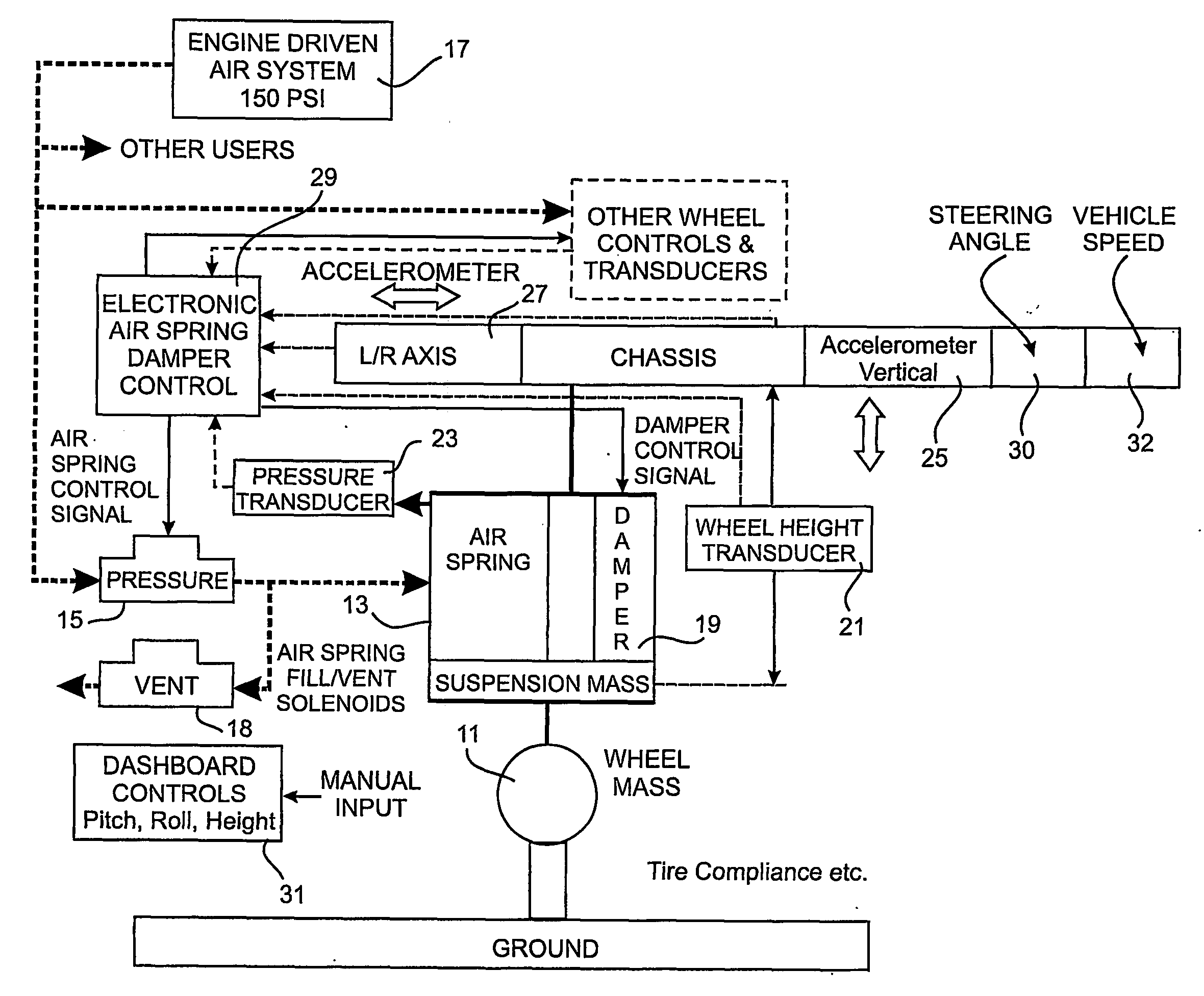
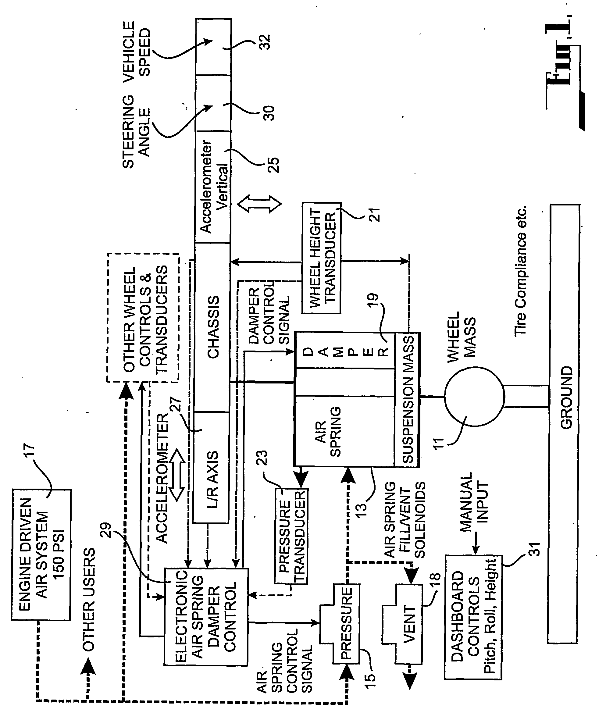
[0032] The embodiments provide an active suspension system that generally maintains the attitude of a vehicle's chassis substantially parallel with a plane of average axle articulation.

[0033] Vehicle suspension systems may be regarded as either active or passive. A typical passenger vehicle has a passive suspension system in which the response to system inputs is dictated by the mechanical properties of the system's springs and dampers. An active suspension systems provides the system with intelligence in the form of sensors, controllers and actuators and attempt to provide response characteristics dictated by control system intelligence.

[0034] Active control systems may be classed as semi-active and fully active. Semi-active control systems utilise both active and passive elements to respond to system inputs. Typically in such systems the passive control compensates for higher frequency inputs such as those associated road surface roughness and the active control compensates for ...


PUM


Abstract

A vehicle suspension control for a vehicle having each wheel (11) supported from the chassis of the vehicle trough a fluid operated extension element (13, 19), the control comprising a controller (27), a plurality of sensors (21, 23, 25, 27, 30, 32), a fluid flow controller (29), a first sensor (21) adapted to sense the relative position between the wheel (11) and the chassis and provide a first output to the controller, a second sensor (23) adapted to sense the pressure of the fluid in each extension element (13, 19) and provide a second output to the controller (27) adapted to receive the output from each of the sensors (21, 23) at each wheel, process the outputs and provide a wheel output to the fluid flow controller (29) for each wheel, the force applied by the extension elements (13, 19) between the chassis and wheels will maintain the attitude of the chassis substantially constant relative to a plane.

Description

FIELD OF THE INVENTION [0001] This invention relates to a vehicle suspension control which is intended to control the suspension system of vehicle. BACKGROUND ART [0002] Conventional vehicle suspension systems are generally passive and usually comprise metallic coil springs supplemented by hydraulic shock absorbers that provide a damping function. The suspension systems are generally used to smooth out vehicle ride action over rough or uneven terrain. In general the vehicle follows the contours of the road and as a result the attitude or departure of the vehicle chassis from the horizontal is a function of the locations of the four wheels supporting the chassis. Therefore if a wheel drops into a pot hole or rides up on a high point then the vehicle will tend to follow the same path. The performance of the conventional style of suspension can be optimised for either the road (smooth terrain) or off-road (uneven terrain) but not both. Off road the vehicle performance is generally comp...

Claims


Application Information

Patent Timeline
29 Mar 2007
Publication
US20070073461A1
IPC
B60G17/018; B60G17/015; B60G17/056; B60G17/08; B60G21/06; B60G21/067; B60G21/073; B60G21/08; B60G23/00; F16F9/50
CPC
B60G17/015; B60G17/0155; B60G17/056; B60G17/08; B60G2300/07; B60G2400/102; B60G2800/01; B60G2400/204
Inventors
FIELDER, NICHOLAS ALBERT WILLIAM