Connector device

a technology of connecting devices and shield shells, applied in the direction of vehicle connectors, coupling device connections, coupling contact members, etc., can solve the problem that the structure is not necessarily reliable in terms of waterproof functionality, and achieve the effect of preventing water penetration through the holding holes in the shield shell and high reliability

Active Publication Date: 2018-06-12
SUMITOMO WIRING SYST LTD +1
View PDF12 Cites 5 Cited by
  • Summary
  • Abstract
  • Description
  • Claims
  • Application Information

AI Technical Summary

Benefits of technology

[0011]As a result, both the first mounting hole of the motor case and the second mounting hole of the inverter case can be sealed with high reliability.
[0015]Because both of the surface seals are pressed by a single shield shell, the structure is simple compared with the case where pressing members are individually provided. In addition, equal surface pressures can be obtained for both of the surface seals.
[0017]By the other axial seal, penetration of water via the holding holes in the shield shell can be prevented. The two motor-side connectors are held in the respective holding holes by friction with the other axial seal in a sub-assembly. The operation for attaching the two motor-side connectors on the upper surface of the motor case can be performed efficiently.
[0018]According to the present invention, mounting holes of both a motor case and an inverter case can be sealed with high reliability.

Problems solved by technology

Accordingly, the structure has not been necessarily sufficiently reliable in terms of waterproof functionality when there is a lack of surface pressure due to molding tolerances of flange thickness, or attaching tolerances of the connectors, for example.

Method used


Image

  • Connector device
  • Connector device
  • Connector device

Examples


Embodiment Construction

[0029]An embodiment of the present invention will be described with reference to FIG. 1 to FIG. 10.

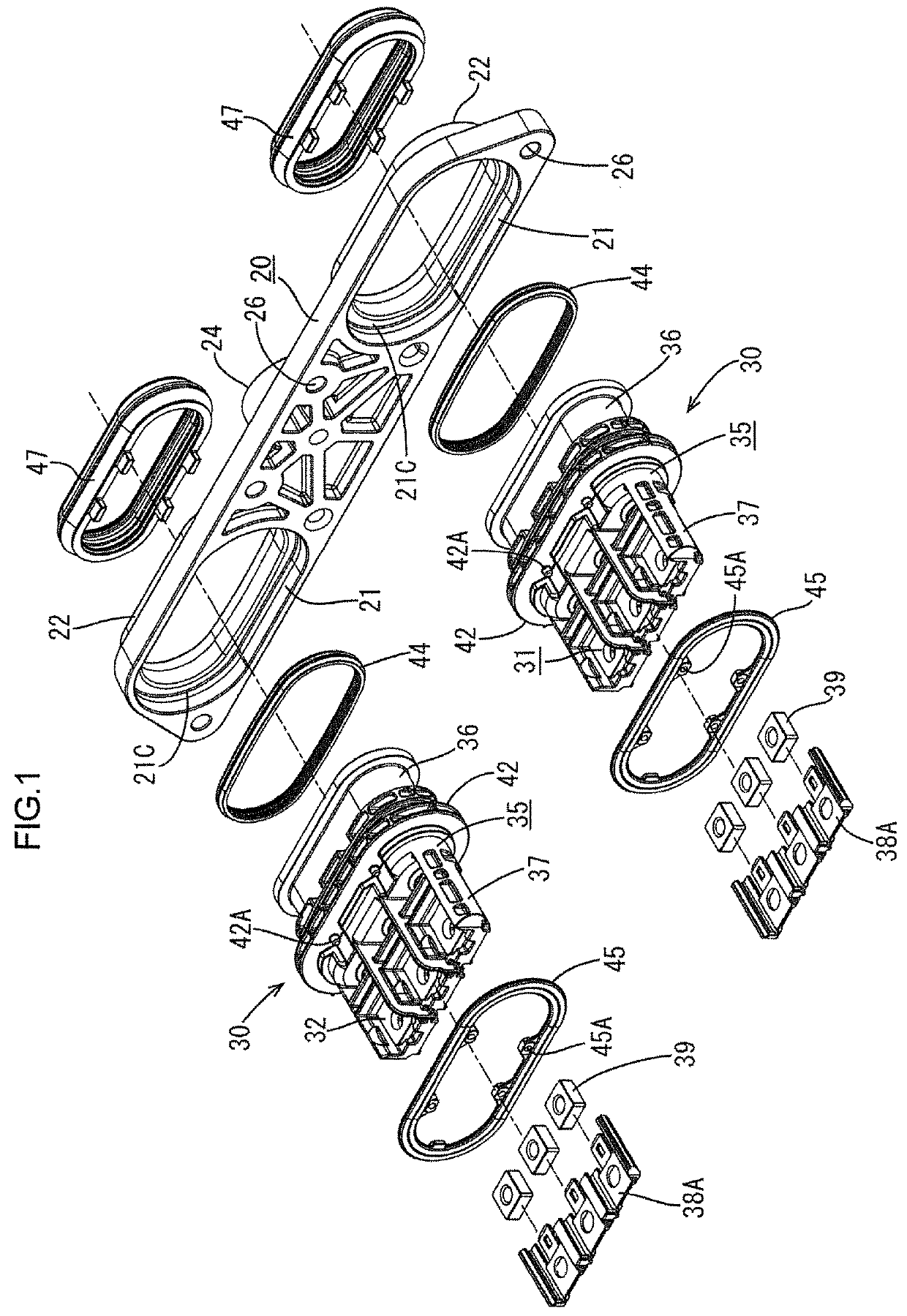
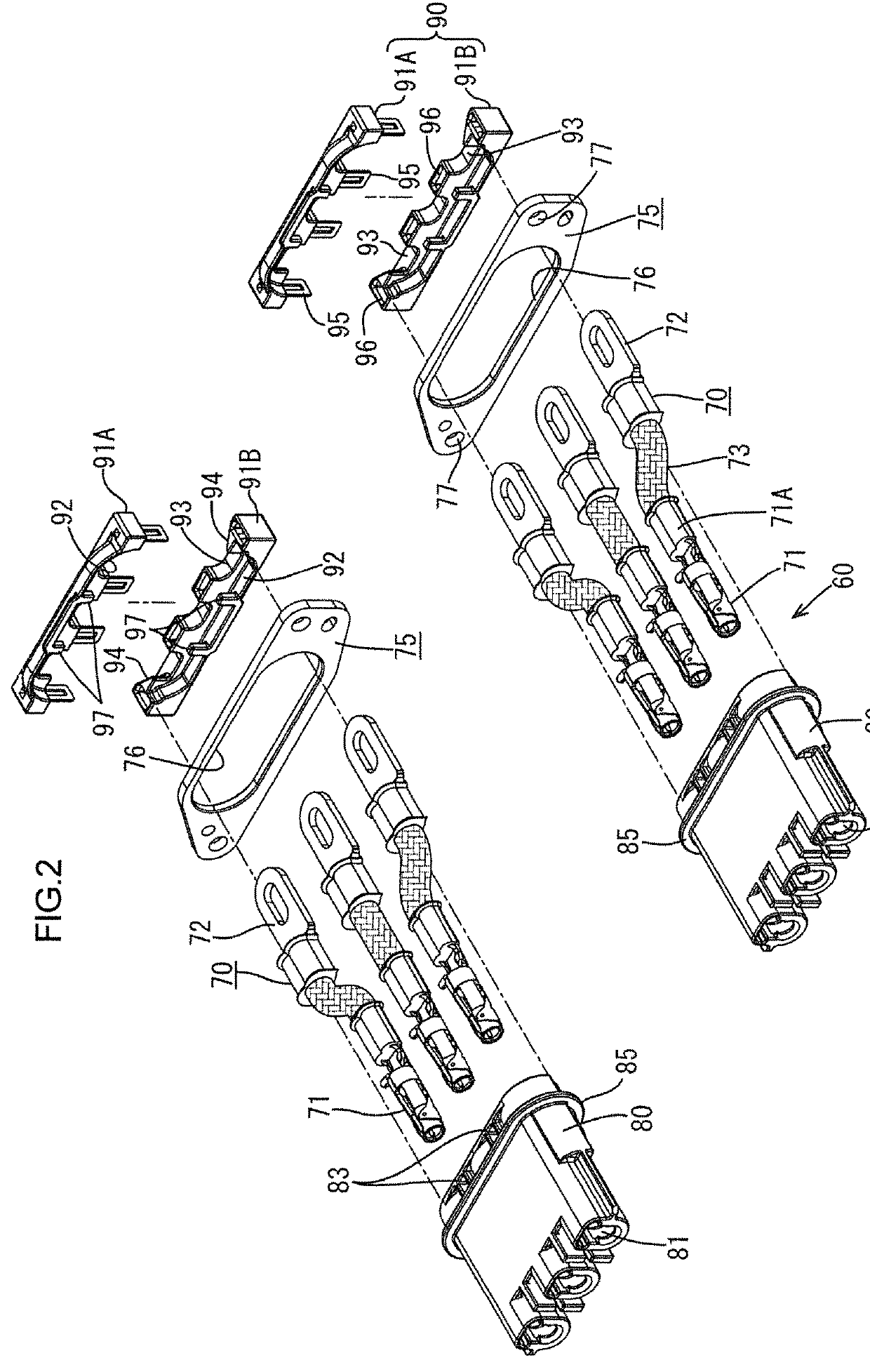
[0030]In this embodiment, as illustrated in FIG. 5, motor-side connectors 30 are attached to a motor case 10 constituting a motor. To an inverter case 50 constituting an inverter PCU (hereafter simply referred to as the inverter), inverter-side connectors 60 are attached, vertically facing the motor-side connectors 30. When the inverter case 50 is placed on the motor case 10 and coupled therewith, the motor-side connectors 30 and the inverter-side connectors 60 are attached to each other.

[0031]In the present embodiment, two motor-side connectors 30 and two inverter-side connectors 60 are provided, each having three poles. In other words, there are provided two, right and left, sets of the motor-side connectors 30 and the inverter-side connectors 60 opposing each other.

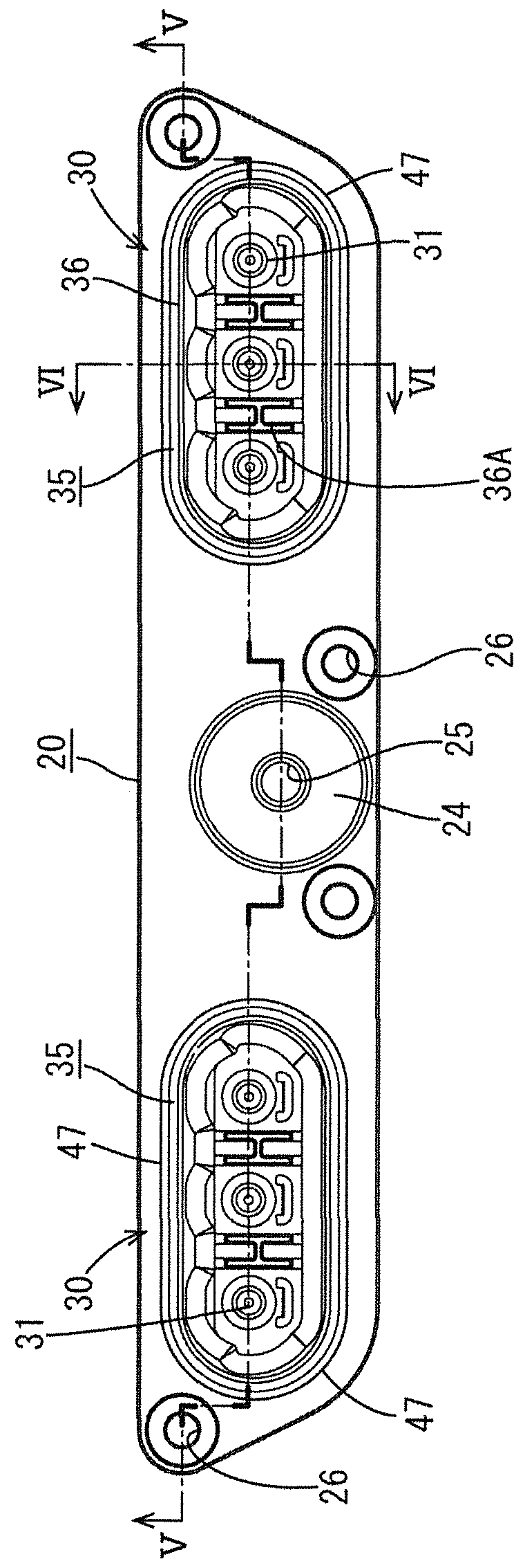
[0032]The motor side will be described. As illustrated in FIG. 1, FIG. 6, and FIG. 7, the motor-side connectors 30 are ...


PUM


Abstract

A motor case (10) has connectors (30) fixed at motor case mounting holes (11), and an inverter case (50) has connectors (60) radially movable at inverter case mounting holes (65). The inverter case (50) is mounted on the motor case (10) so that the connectors (30, 60) fit together. A surface seal (45) is disposed on a lower surface of a flange (42) at an outer periphery of a housing (35) of the motor-side connectors (30), and is compressed elastically against an upper surface of the motor case (10) at an outer periphery of the motor case mounting holes (11). A metal pressing member (20) is fixed on the motor case (10) and presses the flange (42). An axial seal (47) is fit on the outer periphery of the housing (35) and is compressed elastically between the outer periphery and an inner periphery of the second mounting hole (65).

Description

BACKGROUND1. Field of the Invention[0001]The present invention relates to a connector device used for electrically connecting a motor and an inverter.2. Description of the Related Art[0002]In electric vehicles and hybrid vehicles, when a motor and an inverter are electrically connected, motor terminals (connector) and inverter terminals (connector) are conventionally connected using a wire harness.[0003]In recent years, a connector device has been proposed in which, for space saving purposes, for example, a motor-side connector including motor-side terminals in a motor case and an inverter-side connector including inverter-side terminals in an inverter case are disposed opposite each other, and the inverter case is directly connected to the motor case, thereby attaching the respective connectors to each other and connecting the respective terminals. An example of the connector device is disclosed in Japanese Patent Application Laid-Open No. 2011-34935 indicated below.[0004]In this e...

Claims


Application Information

Patent Timeline
Patent Type & Authority Patents(United States)
IPC IPC(8): H02P1/24H02K5/124H02K5/22H01R4/50H01R13/03
CPCH02K5/225H02K5/124H01R13/03H01R13/5202H01R13/5219H01R13/6315H01R13/6581H02K5/10H01R2201/26H02K11/33
Inventor ISHIBASHI, TAKESHIAIBA, TSUKASAHASHIMOTO, TAKAHIDECHOJI, TATSUYA
Owner SUMITOMO WIRING SYST LTD
Why Eureka
Try Eureka