Tire tread mold

a technology of tread molds and rubber, applied in the field of molds, can solve the problems of reducing the service life of the buffer, and forming the mix of films, etc., and achieves the effects of reducing the strain experienced by the deformable buffer, good contact, and increasing the service li

Inactive Publication Date: 2007-04-05
MICHELIN RECH & TECH SA
View PDF6 Cites 16 Cited by
  • Summary
  • Abstract
  • Description
  • Claims
  • Application Information

AI Technical Summary

Benefits of technology

[0023] at least one pin for molding a channel inside the tread, this pin being anchored in one of the lateral parts; and in which, when the mold is closed, a contact surface is formed between the pin and the rib and the pin and / or the rib comprise at least one buffer made of a deformable material, deformation of which makes it possible to fill in the clearance between the pin and the rib at the contact surface when the mold is closed.
[0024] The presence of the buffer has the advantage of preventing any air from being enclosed between the pin and the rib. Generally speaking, fixing the buffer on the rib (rather than on the pin) has the advantage that the buffer experiences less strain and friction when the pin is withdrawn from the molded tire, which increases its service life.
[0033] According to a first preferred embodiment, the contact surface between the pin and the rib comprises a first part and a second part, the first part being substantially perpendicular to the radial direction and the second part being inclined with respect to the first part, and the buffer fills the clearance between the pin and the rib at said second part of the contact surface. The first and second parts are preferentially flat, as this allows a good contact between the pin and the rib. The angle of inclination α between the first part and the second part, measured in a plane comprising both the radial direction and the mean direction of the pin (see FIGS. 8 and 18) is preferentially greater than 45° and even more preferentially greater than 70°. This embodiment allows to reduce the strain experienced by the deformable buffer when the mold is closed. At that moment, the radial forces exerted upon the assembly formed by the pin and the corresponding rib are mainly taken up by the first part. The buffer that covers the second part, which is inclined with respect to the radial direction, undergoes little or no strain, which significantly increases its service life. This is true irrespective of whether the buffer is integral with the pin or with the rib.
[0034] According to a second preferred embodiment, the buffer is integral with the rib and has the shape of a strip, extending, for example, in a direction that is substantially perpendicular to the radial direction, such that it may serve as a support for a plurality of pins. This embodiment allows to reduce the manufacturing cost of the mold, in particular when a great number of pins is used. Moreover, as the buffer is fixed on the rib, there is more space and a thick buffer may be used, which allows to make up for more severe misalignment of pins.
[0035] According to a third preferred embodiment, the buffer comprises a deformable zone and a docking zone made of rigid material, preferably of metal, which is intended to come in contact with the pin. This makes it possible to avoid any direct contact between the pin and the deformable material, with the intention of reducing the friction suffered by the material, and, consequently, of increasing the buffer's service life. Preferentially, the buffer further comprises a rigid, preferably metallic, fixing zone for fixing the buffer on the rib, for example by means of a thread. In this embodiment, the deformable zone is sandwiched between the fixing zone and the docking zone.
[0036] The deformable buffer may be made of a plastic material (such as a metal foam) or an elastic material (such as for example silicone). According to a preferred embodiment, the deformable buffer is made of an elastic material, because this characteristic makes it possible to prevent the formation of any clearance between pin and rib even after a plurality of molding stages. If deformation is purely plastic, the buffer will not be in a position to ensure compensation of the clearance stemming from wear of the molding elements or due to assembly. It is thus advantageous to use materials whose deformation has an elastic component. Preferably, a material will be used which is both elastic and incompressible, such as silicone.

Problems solved by technology

The clearance necessary for positioning the pins in the support results in the formation of films of mix.
Moreover, the rotational movement imposed on each pin to unscrew it has the effect of shearing and thus breaking the films formed between each pin and the pin passages.
One disadvantage of this solution consists in the fact that it requires means for screwing in and unscrewing each pin, so rendering molding and unmolding very complex.
Another drawback of the solution lies in the fact that it creates constraints with regard to the geometry of each pin, because the threaded zones are necessarily cylindrical.

Method used


Image

  • Tire tread mold
  • Tire tread mold
  • Tire tread mold

Examples


Embodiment Construction

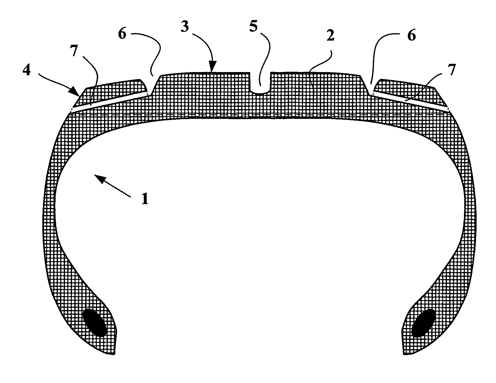
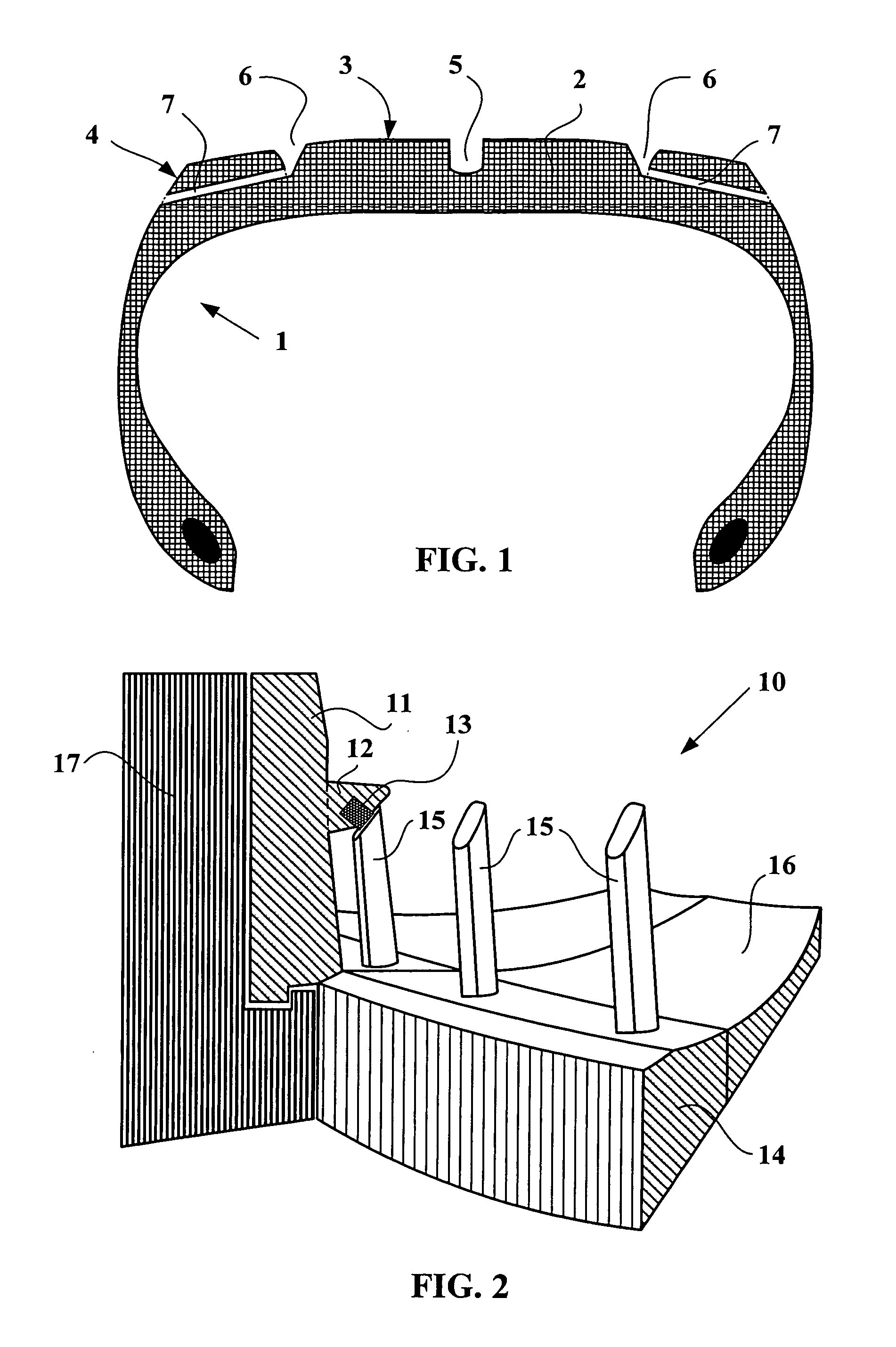
[0053]FIG. 1 is a schematic representation of a partial view in radial section of a tire 1 provided with a tread 2 comprising a running surface 3 delimited axially by lateral faces 4. The tread has a central groove 5; other grooves 6 are also disposed over the section. These grooves 6 are connected to the lateral faces 4 by means of channels 7.

[0054]FIG. 2 is a schematic representation of a partial perspective view of a mold 10 according to the invention allowing to obtain a tire 1 provided with channels 7 opening both onto a lateral face 4 of the tread 2 and onto at least one lateral wall of at least one groove 6 of the tread 2 without being closed up by a film of mix.

[0055] The Figure shows the central part 11 intended for molding the running surface 3 provided with a rib 12 comprising a deformable buffer 13. Also shown is a lateral part 14 intended for molding the lateral face 4 of the tread 2. The pins 15 are integral with this lateral part 14. FIG. 2 shows the mold 10 in its ...


PUM

PropertyMeasurementUnit
molding pressuresaaaaaaaaaa
angle of inclinationaaaaaaaaaa
diameteraaaaaaaaaa

Abstract

A mold for molding a tread of rubber mix, this tread comprising a running surface delimited axially by lateral faces, this mold comprising (i) a central part for molding the running surface, movable between an open configuration allowing filling of the mold and a closed configuration allowing molding, the central part comprising at least one rib for molding a groove in the running surface; (ii) two lateral parts for molding the lateral faces, at least one of the lateral parts being axially movable relative to the central part; et (iii) at least one pin for molding a channel inside the tread, this pin being anchored in one of the lateral parts; and in which, when the mold is closed, a contact surface is formed between the pin and the rib, and the pin and / or the rib comprise a buffer made of a deformable material, deformation of which makes it possible to fill in the clearance between the pin and the rib at the contact surface when the mold is closed.

Description

BACKGROUND OF THE INVENTION [0001] 1. Field of the Invention [0002] The present invention relates to molds allowing the molding of tires or of treads. DEFINITIONS [0003] In the present document, the terms “axial” and “axially” designate a direction substantially parallel to the axis of rotation of a tire, or, if these terms are applied to a tread which has not as yet been fixed to a tire, a direction intended to be substantially parallel to the axis of rotation of a tire once the tread is fixed to the tire. A point of a tread is said to be axially to the outside of a second point of the same tread if the first point is axially further from the median plane of the tread. [0004] The terms “radial” and “radially” here designate any direction perpendicular to the axis of rotation of the tire and intersecting this axis, or, if these terms are applied to a tread which has not as yet been fixed to a tire, any direction intended to be perpendicular to the axis of rotation of the tire and in...

Claims


Application Information

Patent Timeline
Patent Type & Authority Applications(United States)
IPC IPC(8): B29D29/00B29D30/00
CPCB29C33/0033B29C33/44B29D30/0606B29D2030/061B29L2030/00
Inventor DELBET, CEDRICDESVIGNES, JEAN-CLAUDEKNEPFLE, ROBERT W.
Owner MICHELIN RECH & TECH SA
Why Eureka
Try Eureka