Implant

a technology of implants and proximal implants, applied in the field of implants, can solve the problems of not being suitable for intervertebral implants, cannot be inserted in a minimally invasive manner, and their size, and achieve the effect of reducing the healing period and being simple to produ

Inactive Publication Date: 2006-01-12
AESCULAP AG
View PDF17 Cites 16 Cited by
  • Summary
  • Abstract
  • Description
  • Claims
  • Application Information

AI Technical Summary

Benefits of technology

[0008] As a result of the configuration of the plurality of cavities in fluidic connection with one another, the implant has a frame-like structure, which assures optimum dimensional stability. No overall deformation of the implant such as in the case of the known balloons results particularly when filling the cavities in fluidic connection with one another with a fluid. Moreover, such an implant can be brought in a simple manner from the normal position into the insertion position, e.g. by compression, and can thus be inserted into the body of a human or an animal in a minimally invasive manner and be used as a bone replacement implant or an intervertebral implant.
[0023] It is particularly advantageous if the insertion volume amounts at maximum to 20 per cent of the maximum total volume. This allows a surgical access point to be reduced in size by up to 80 per cent compared with conventional non-compressible implants. This causes substantially less strain on a patient and reduces the healing period for a surgical wound required for access to the surgical site.

Problems solved by technology

The disadvantage with such implants has proved to be their size, i.e. they cannot typically be inserted in a minimally invasive manner.
The disadvantage with such implants is that they are not at all suitable as intervertebral implants, since such a balloon implant always expands in the direction of least resistance, particularly upon filling with a fluid.

Method used


Image

  • Implant
  • Implant
  • Implant

Examples


Embodiment Construction

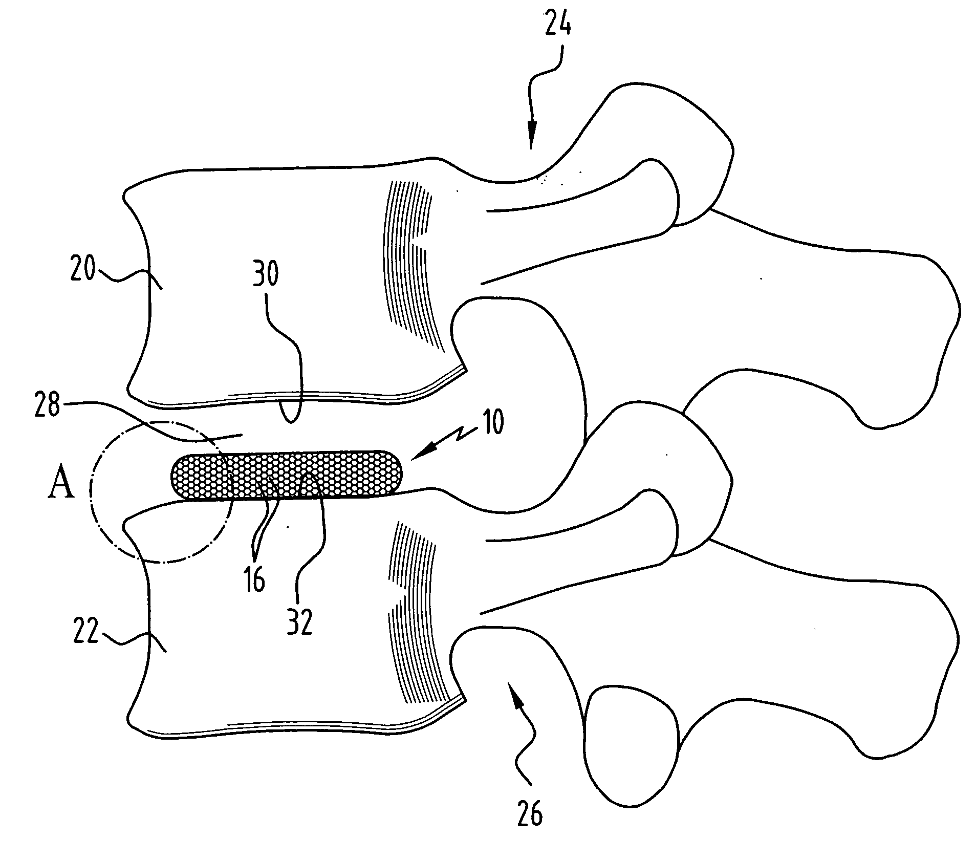
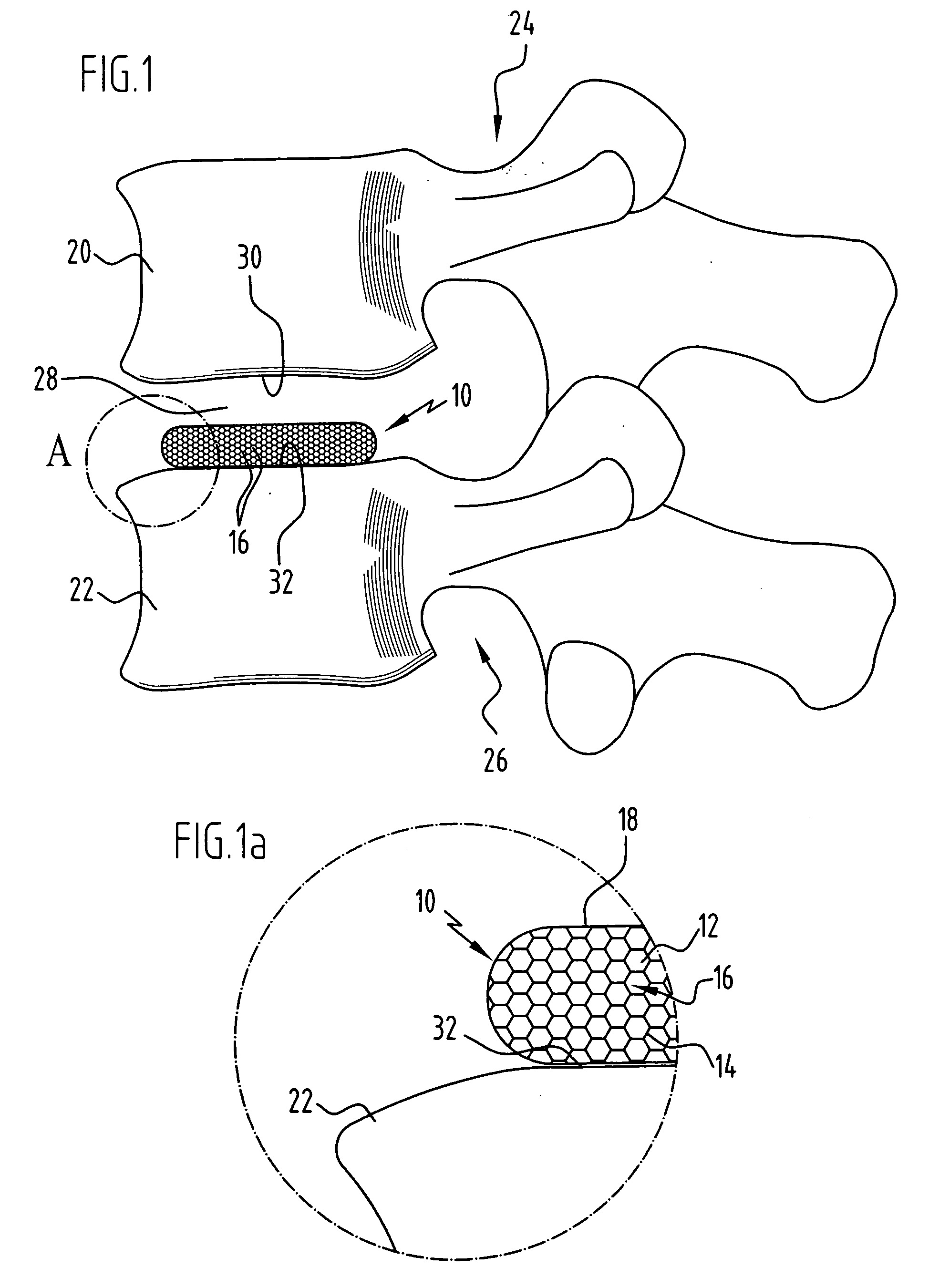
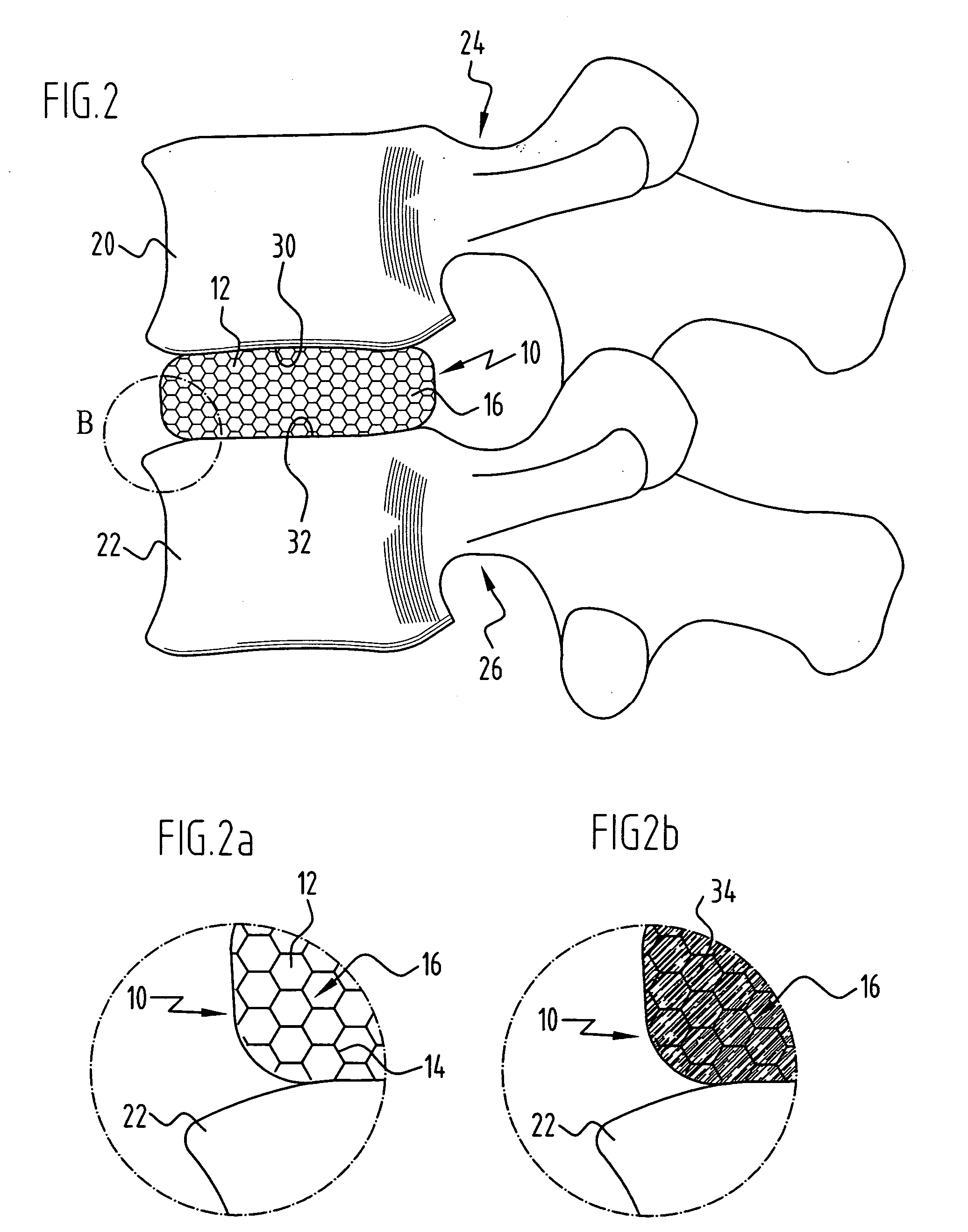
[0030]FIGS. 1 and 2 show an implant according to the invention, given the overall reference 10, in the form of an intervertebral implant for replacement of a completely removed natural intervertebral disc. The implant 10 has a sponge-like structure, i.e. it comprises a plurality of cavities 12, which are enclosed by chamber walls 14 and thus form a plurality of implant chambers 16, as is clearly evident in FIG. 1a. The implant chambers 16 are each in fluidic connection with implant chambers 16 adjacent to them. An outer surface of the implant 10 is covered with a film 18 of polylactide, which thus forms a sheath for the implant as a whole.

[0031] The implant 10 is elastic overall, in particular the chamber walls 14 are formed from a bioresorbable material, e.g. collagen, gelatine, a polymer nonwoven, a polymer foam, hyaluronic acid, a hyaluronic acid derivative or a mixture of two or more of the named materials. The cavities 12 are shown with a honeycombed form in the figures. Irreg...


PUM

PropertyMeasurementUnit
volumeaaaaaaaaaa
volumeaaaaaaaaaa
average volumeaaaaaaaaaa

Abstract

In order to improve an implant, in particular a bone replacement implant for insertion into a bone cavity, or an intervertebral implant for insertion between two adjacent vertebral bodies of a human or animal spine, which can be brought from a normal position, in which the implant encompasses a maximum total volume, into an insertion position, in which the implant encompasses an insertion volume, which is smaller than the maximum total volume, such that the implant can be inserted through as small as possible an opening in a human or animal body and nevertheless have a high inherent stability, it is proposed that the implant has a plurality of cavities in fluidic connection with one another, and that a net volume encompassed in the normal position by the plurality of cavities in fluidic connection with one another is smaller than the maximum total volume.

Description

[0001] The present disclosure relates to the subject matter disclosed in German application number 10 2004 030 347.9 of Jun. 18, 2004, which is incorporated herein by reference in its entirety and for all purposes. BACKGROUND OF THE INVENTION [0002] The present invention relates to an implant, in particular a bone replacement implant for insertion into a bone cavity formed by resection, for example, or an intervertebral implant for insertion between two adjacent vertebral bodies of a human or animal spine, which can be brought from a normal position, in which the implant encompasses a maximum total volume, into an insertion position, in which the implant encompasses an insertion volume, which is smaller than the maximum total volume. [0003] For treatment of a disc prolapse, the affected intervertebral disc is usually partially or completely removed and the section of the spine formed by the two vertebrae adjacent to the damaged disc reinforced. To achieve such a reinforcement, the t...

Claims


Application Information

Patent Timeline
Patent Type & Authority Applications(United States)
IPC IPC(8): A61F2/44
CPCA61F2/30767A61F2/30771A61F2/442A61F2002/30062A61F2002/30144A61F2230/0017A61F2002/30911A61F2002/30919A61F2002/3092A61F2002/4631A61F2210/0004A61F2002/30579A61F2002/30143
Inventor BLOEMER, WILHELMBEGER, JENSFINK, ULRICHWAGNER, CECILE
Owner AESCULAP AG
Why Eureka
Try Eureka