
Highly absorbent composite and method of making the same

a composite and high-absorption technology, applied in the field of new-type absorbent composites, can solve the problems of no successful commercialization examples reported, no effective absorbent products have been developed, and initial absorbing is very fast, so as to achieve high viscosity, improve the effect, and hold stably in a small spa

Inactive Publication Date: 2010-03-11
SUZUKI MIGAKU +2
View PDF11 Cites 81 Cited by
  • Summary
  • Abstract
  • Description
  • Claims
  • Application Information

AI Technical Summary

Benefits of technology

[0020]A second embodiment of the present invention provides an absorbent sheet, wherein a supporting sheet and an absorbent layer provided on at least either surface of the supporting sheet are provided and wherein the absorbent layer has the HFFM, the SAP particles, and a short-cut staple fiber component having longer fiber length than the average particle diameter of the SAP particles and has an improved dimensional stability when wet swollen.
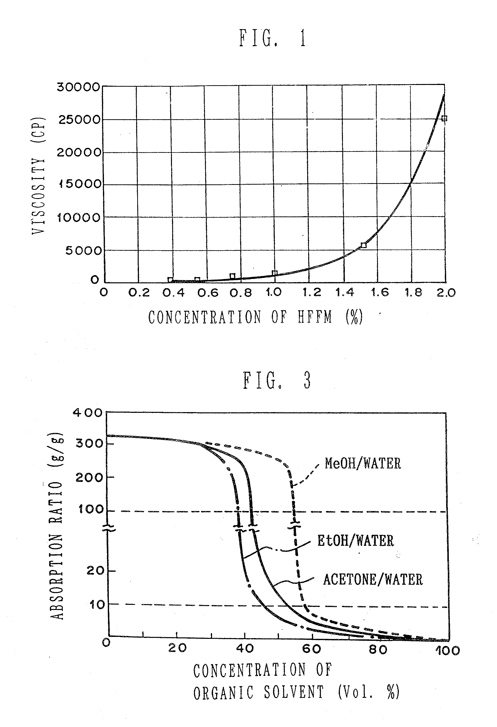
[0099]A manufacturing process can be efficiently designed through incorporating this change in viscosity successfully in the process. However, a drawback of polyvalent alcohol solvents is that, because they show a high viscosity even when they contain water, they may cause uneven coating in coating a substrate sheet material because they do not fit well with the substrate material due to their hardly penetrating the material. In such case, adding of methanol or ethanol to combine with this polyvalent alcohol solvent, for example, applying of a three-component system, PG / ethanol / water, may be effective.

Problems solved by technology

Thus, the absorbent product does not work as designed.
However, so far, no successfully commercialized examples have been reported because of high costs of raw materials and high capital investments involved.
However, an absorbent product in which the content of the SAP is made high or the SAP alone is used in order to secure high absorbency has a serious drawback; upon a liquid being discharged at first the SAP starts to absorb it all at once and thus an initial absorbing is very speedy but as the discharging is repeated, the absorbing speed drastically decreases.

Method used

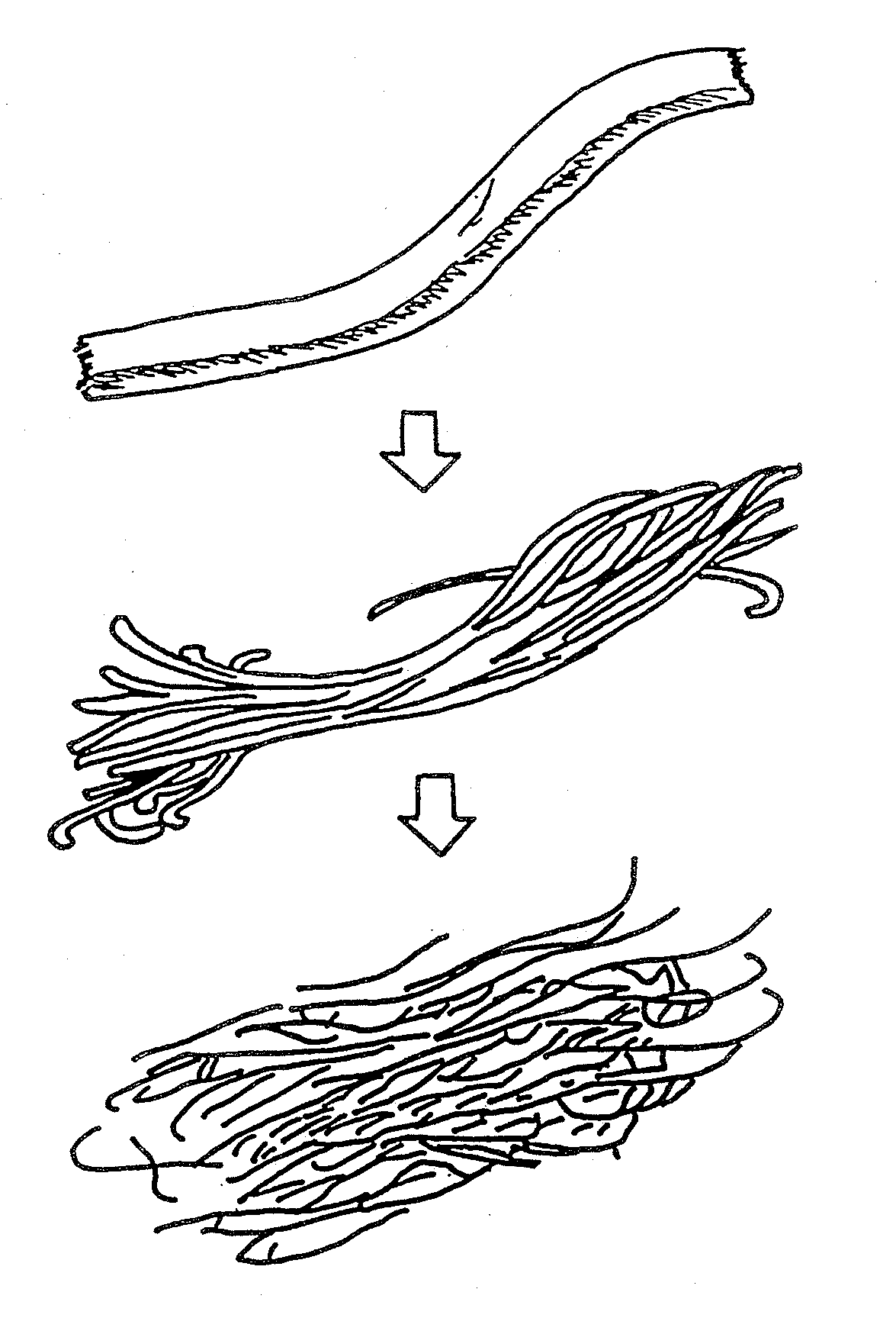
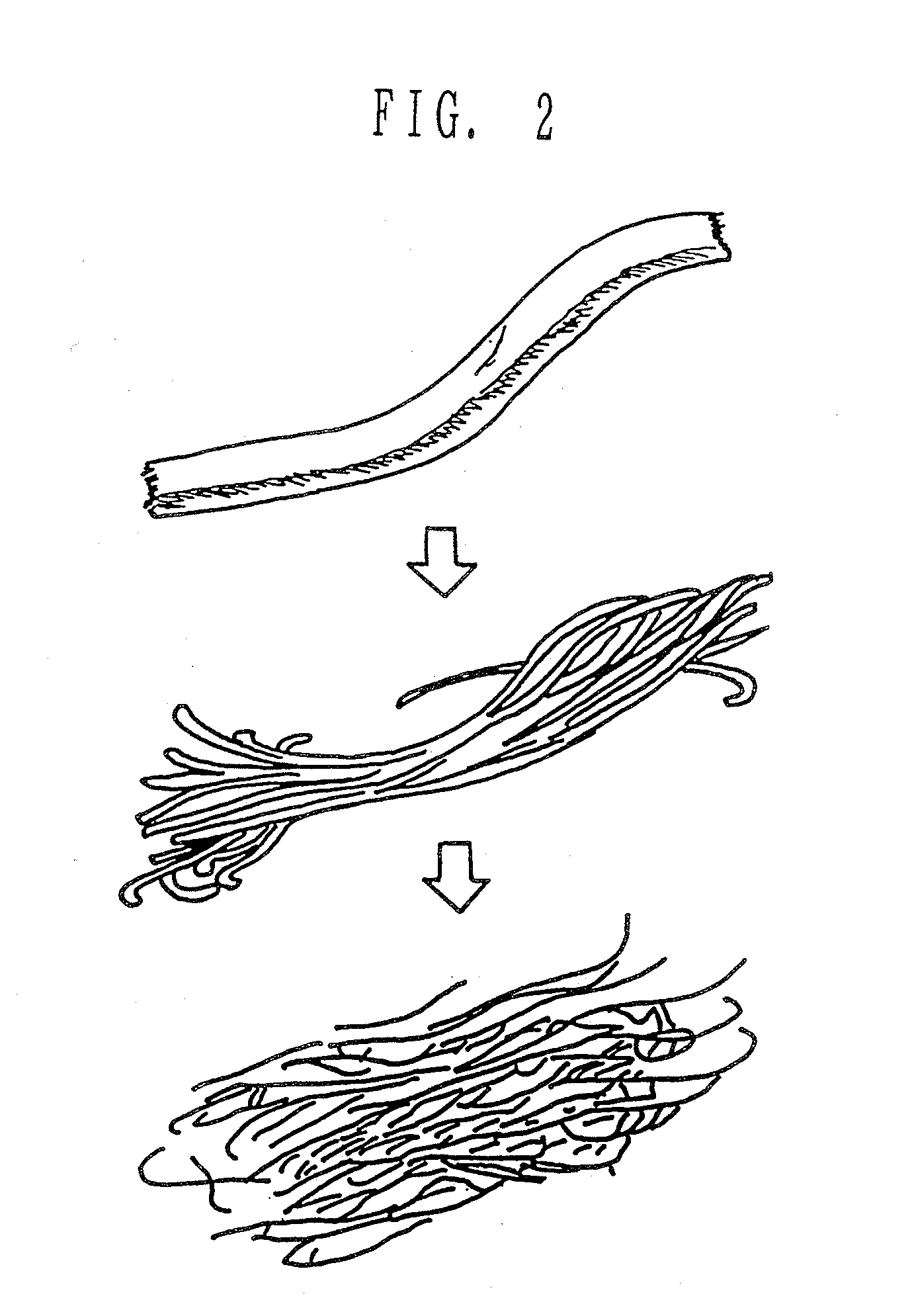

Image

  • Highly absorbent composite and method of making the same
  • Highly absorbent composite and method of making the same
  • Highly absorbent composite and method of making the same

Examples


example 1

Preparing the HFFM Dispersion Liquids

[0310]Ethyl alcohol and ion-exchanged water were added to a dispersion liquid of the S-MFC (made by Tokushu Paper Mfg. Co., Ltd.) in gel state of 3.0% water dispersion as a stock liquid, to make three kinds of microfibril dispersion liquid where the ratio of ethyl alcohol / water was 70 / 30 and the concentrations of the S-MFC were 0.25%, 0.5% and 1%, respectively.

Preparing the HFFM / SAP Coexistent Dispersion Liquids

[0311]10 grams of the SAP (made by Sanyo Chemical Industries, Ltd. under the trademark “IM-6700”) passed by 60 to 100 mesh was added to 50 cc of each of the above-mentioned three kinds of the HFFM dispersion liquid to prepare the HFFM / SAP dispersion slurry.

[0312]The prepared dispersion slurry is described as follows:

TABLE 2ExperimentEthylConcentrationS-MFC / SAP ×No.alcohol / waterof S-MFC (%)100 (%)No. 170 / 300.20.1No. 270 / 300.52.5No. 370 / 301.05.0

Forming the HFFM / SAP Composite Sheet Material

[0313]Each of the dispersion liquids while stirred wa...

example 2

Concentration of the HFFM and the Properties of a Composite Sheet Material

[0318]Preparing the HFFM Dispersion Liquid

[0319]Preparing a Bacteria Cellulose (BC) Stock Solution

[0320]BC (made by B.P.R.) where the concentration of solids was 30% was stirred and dissolved in ion-exchanged water by a mixer for approximately 2 hours to prepare a stock solution where the concentration of solids was 1.2%.

Preparing Ethyl Alcohol / Water Dispersion Liquids of BC

[0321]Ethyl alcohol and water were added to a prescribed amount of the stock solution to prepare BC dispersion liquids of 0.02% to 0.80% BC.

Preparing the HFFM / SAP Coexistent Dispersion Liquid

[0322]5 grams of the SAP (made by Sanyo Chemical Industries, Ltd.) was added to 50 cc of each of the dispersion liquids of 0.02% to 0.8% BC to prepare BC / SAP dispersion liquids. In case the concentration of the BC was lower in the dispersion liquid, the SAP settled, but as the concentration of the BC became higher, it became stabilized. By stirring with...

example 3

Continuous Coating Experiments

[0328]A highly absorbent composite was made by using an apparatus as shown in FIG. 61 provided with a coating unit as shown in FIG. 63, using the following materials:

(1) Microfibril: S-MFC (made by Tokushu Paper Mfg. Co., Ltd.)

(2) SAP: 1M-4000 (made by Hoechst-Celanese Co.)

(3) Suspension medium: Acetone / water system

(4) Coating composition:

Component% by weightS-MFC0.4SAP30.0Acetone48.8Water20.8

(5) Supporting sheet: A two-layered through-air thermal bond web non-woven fabric (40 g / cm2, apparent specific density of 0.06) having the following composition was used:

[0329]Upper layer: Mixed web of rayon (4 denier×45 mm length (70%)) and PE / PET (2 denier×45 mm length (30%)), approximately 25 g / cm2

[0330]Lower layer: Single web of PE / PET bicomponent fiber (2 denier×45 mm length), approximately 15 g / cm2.

[0331]A mixture dispersion liquid of the composition in (4) above was continuously applied in approximately 10 mm width at an interval of 5 mm width onto the surf...


PUM

PropertyMeasurementUnit
Percent by massaaaaaaaaaa
Fractionaaaaaaaaaa

Abstract

A composite structure mainly composed of hydratable fine fibers in the form of microfibril and a water swellable solid body, the fibers being obtained from cellulose or derivatives thereof, and at least part of the surface of the solid body is covered with the fine fibers. The absorbent composite can be formed in various form of, for example, particle, pellet, sheet and the like, especially of a sheet type with a supporting sheet of a non-woven fabric. The present invention further provides a method of making the composite structure.

Description

[0001]This application is a division of U.S. patent application Ser. No. 09 / 242,482 filed Oct. 22, 1999 entitled “Highly Absorbent Composite Compositions, Absorbent Sheets Provided with the Compositions, and Process for Producing the Same” which is a 371 application of PCT / JP97 / 04606 filed Dec. 15, 1997 which claims priority of Japanese Patent Application Number 333520 / 1996 filed Dec. 13, 1996 and Japanese Patent Application Number 124623 / 1997 filed May 15, 1997 and Japanese Patent Application Number 192159 / 1997 filed Jul. 17, 1997 and Japanese Patent Application Number 213222 / 1997 filed Aug. 7, 1997 and Japanese Patent Application Number 313368 / 1997 filed Nov. 14, 1997 and Japanese Patent Application Number 329830 / 1997 filed Dec. 1, 1997, all the disclosures of which are herein incorporated by reference.BACKGROUND OF THE INVENTION[0002]1. Field of the Invention[0003]The present invention relates to a new type absorbent composite wherein a water swellable solid body, particularly co...

Claims


Application Information

Patent Timeline
IPC IPC(8): B01J20/24A61F13/15A61L15/22C08L1/02A61L15/28A61L15/60B29C70/34D06M15/05
CPCA61F13/53Y10T428/1386A61F2013/530145A61L15/28A61L15/60C08K7/02D06M15/05D06M15/07D06M23/08D06M23/10D06M23/16D21H21/22Y10T428/1348Y10T428/1352Y10T428/139Y10T428/296Y10T428/1314Y10T428/13Y10T428/1393Y10T428/1303Y10T428/1359Y10T428/1362A61F13/5323Y10T428/23993Y10T428/23936Y10T428/23921Y10T428/23929Y10T428/23979A61L15/12
Inventor SUZUKI, MIGAKUMATSUMOTO, RYOICHIMORI, SHINGO
Owner SUZUKI MIGAKU
Learn More