Press roll device

Inactive Publication Date: 2001-09-04
LES PRODN GIBERGO
View PDF19 Cites 14 Cited by
  • Summary
  • Abstract
  • Description
  • Claims
  • Application Information

AI Technical Summary

Benefits of technology

It is also an object of the present invention to provide such a device which has a better response time to unevenness in the piece of wo

Problems solved by technology

The jack often fails to react quickly enough to the bigger bumps on the wood's surface, te

Method used


Image

  • Press roll device
  • Press roll device
  • Press roll device

Examples


Example

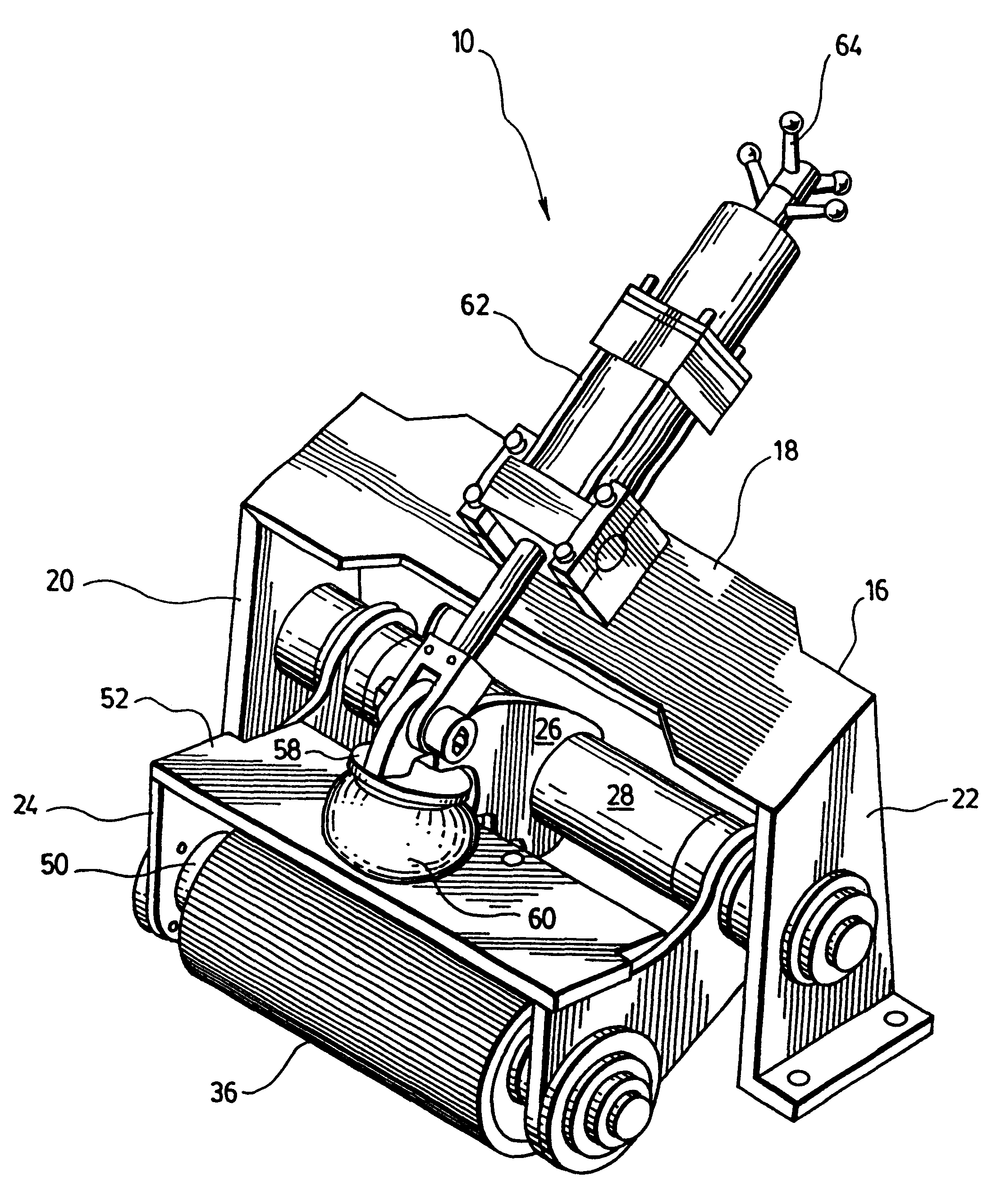
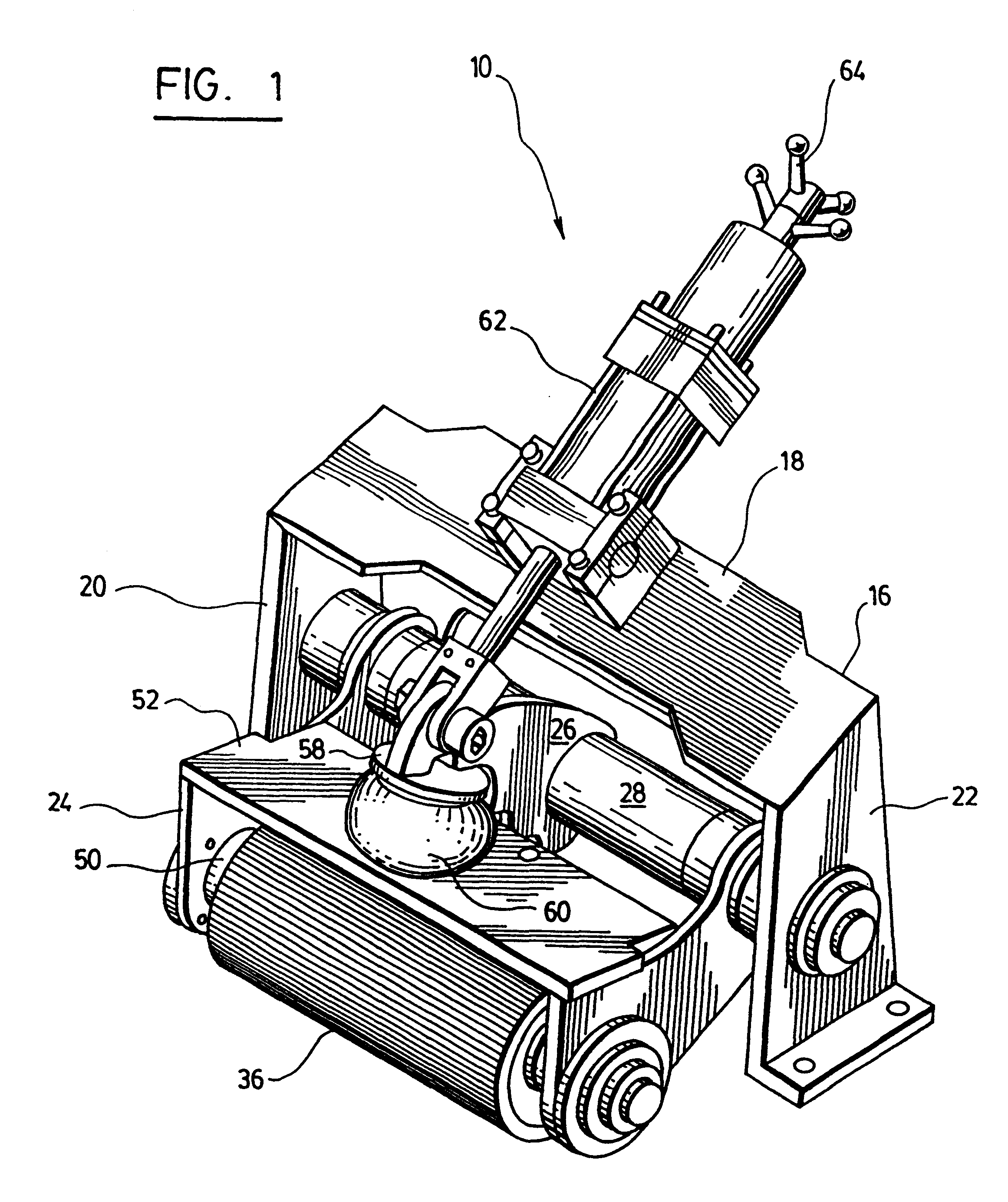
With reference to FIGS. 1 to 4, there is shown a press roll device 10 in accordance with a preferred embodiment of the present invention. The device 10 is used for applying pressure on a piece of wood 12 moving along a path 14. In the illustrated embodiment, the action of the roller is the force used to push the piece of wood 12 along the path 14. Alternatively, the piece of wood 14 may be carried on a conveyor and the press roll device, motorized or not, is used only to keep it on the path 14.

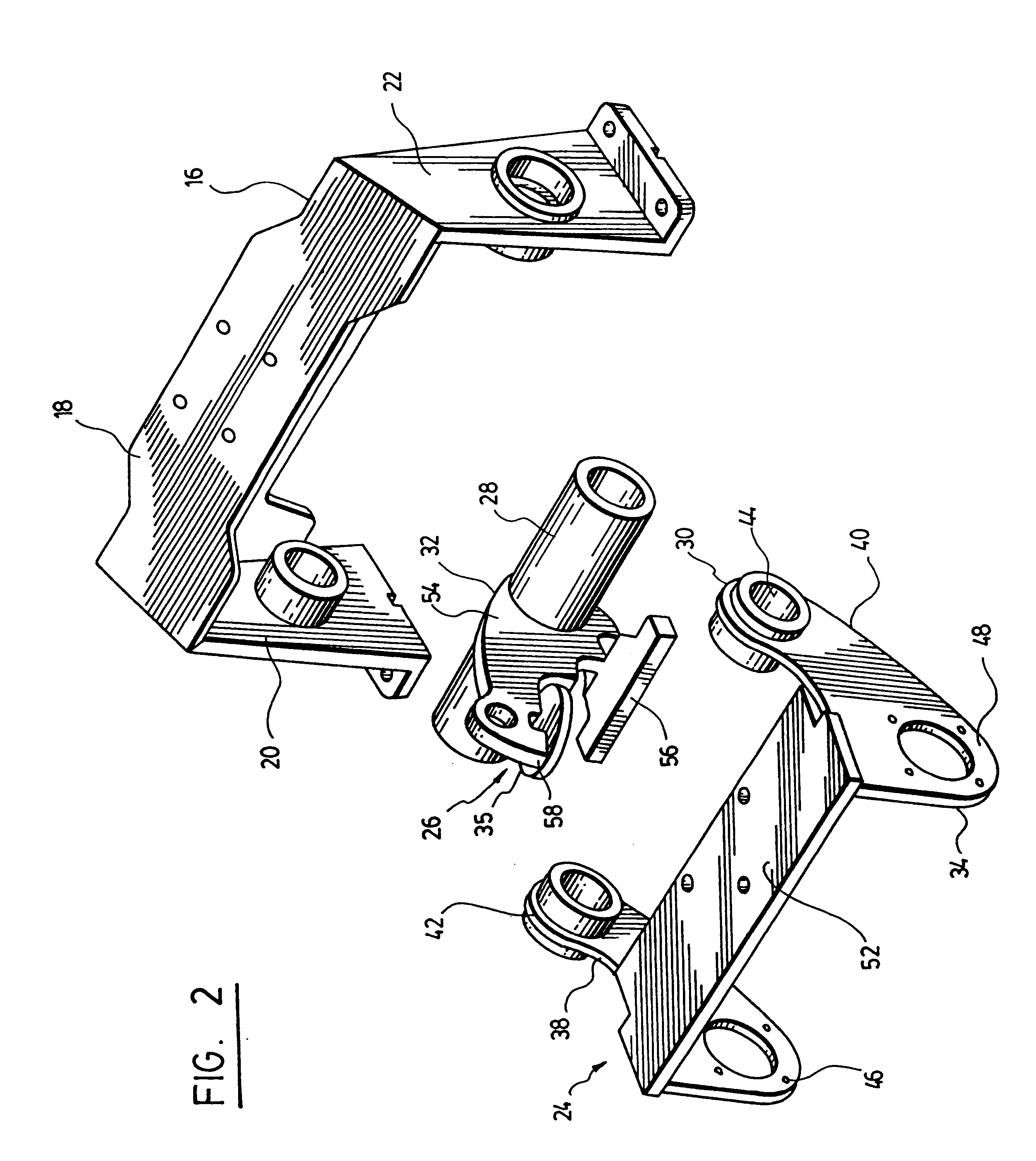
Referring more particularly to FIGS. 1 and 2, the device 10 has a frame 16 which is mounted in proximity to the path of the piece of wood. The frame 16 preferably has a top wall 18 and two generally parallel side walls 20 and 22. The device further includes a lower arm 24 and an upper arm 26, both pivotally connected to the frame 16. In the preferred embodiment, the frame includes a main shaft 28 extending between the side walls 22 and 24, each of the lower and upper arms 24 and 26 having a fi...


PUM


Abstract

A press roll device for applying pressure on a piece of wood moving along a path. The device has a frame mounted in proximity to the path of the piece of wood and a lower and an upper arm both pivotally connected to the frame. A roller is rotationally mounted on the end of the lower arm and a jack is resiliently connected to the corresponding end of the upper arm. A bag of compressed air is disposed between the ends of the lower and upper arm, resiliently separating the roller and the jack. In this manner, the bag of compressed air absorbs the vibration of the roller caused by unevenness in the piece of wood, at least partially.

Description

The present invention relates to the field of machinery for the wood processing industry and particularly concerns a press roll device for applying pressure on a moving piece of wood.Pieces of wood of all kinds moving through wood processing machinery need to be carried at a controlled speed and to follow a well defined path to be properly processed. There is known in the art to provide conveying systems with a motorised pressing roll mounted on a pivoting frame. The press roll both moves the wood along its path and applies a pressure thereon to keep it on track. The pivoting movement of the frame is resiliently controlled, for example, through a pneumatic or a hydraulic jack. In these systems a lot of strain is imposed on the jack since its movement has to compensate for the unevenness of the wood surface and keep the pressure thereon constant. The jack often fails to react quickly enough to the bigger bumps on the wood's surface, temporarily loosing its grip on the piece of wood w...

Claims


Application Information

Patent Timeline
IPC IPC(8): B27B25/02B27B25/00B27C1/00B27B31/00B27C1/12
CPCB27B25/02B27C1/12B27B31/003
Inventor GILBERT, SYLVAIN
Owner LES PRODN GIBERGO
Why Eureka
Try Eureka