Vehicle power source device

A technology for power supply devices and vehicles, which is applied in the direction of circuit devices, battery circuit devices, and vehicle energy storage, and can solve problems such as difficulty in checking battery status

Active Publication Date: 2005-11-16
PANASONIC CORP
View PDF1 Cites 8 Cited by
  • Summary
  • Abstract
  • Description
  • Claims
  • Application Information

AI Technical Summary

Problems solved by technology

However, even if the battery is regularly replaced in advance, it is difficult to check the state of the battery every day or every time the vehicle starts running, and it is necessary to further improve safety

Method used


Image

  • Vehicle power source device
  • Vehicle power source device
  • Vehicle power source device

Examples


Embodiment Construction

[0012] Hereinafter, embodiments of the present invention will be described with reference to the drawings.

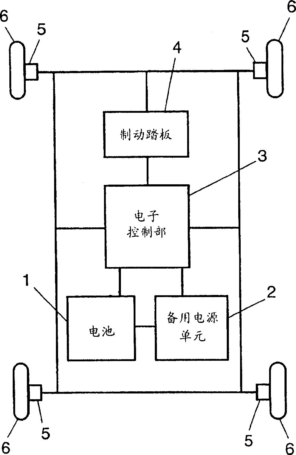
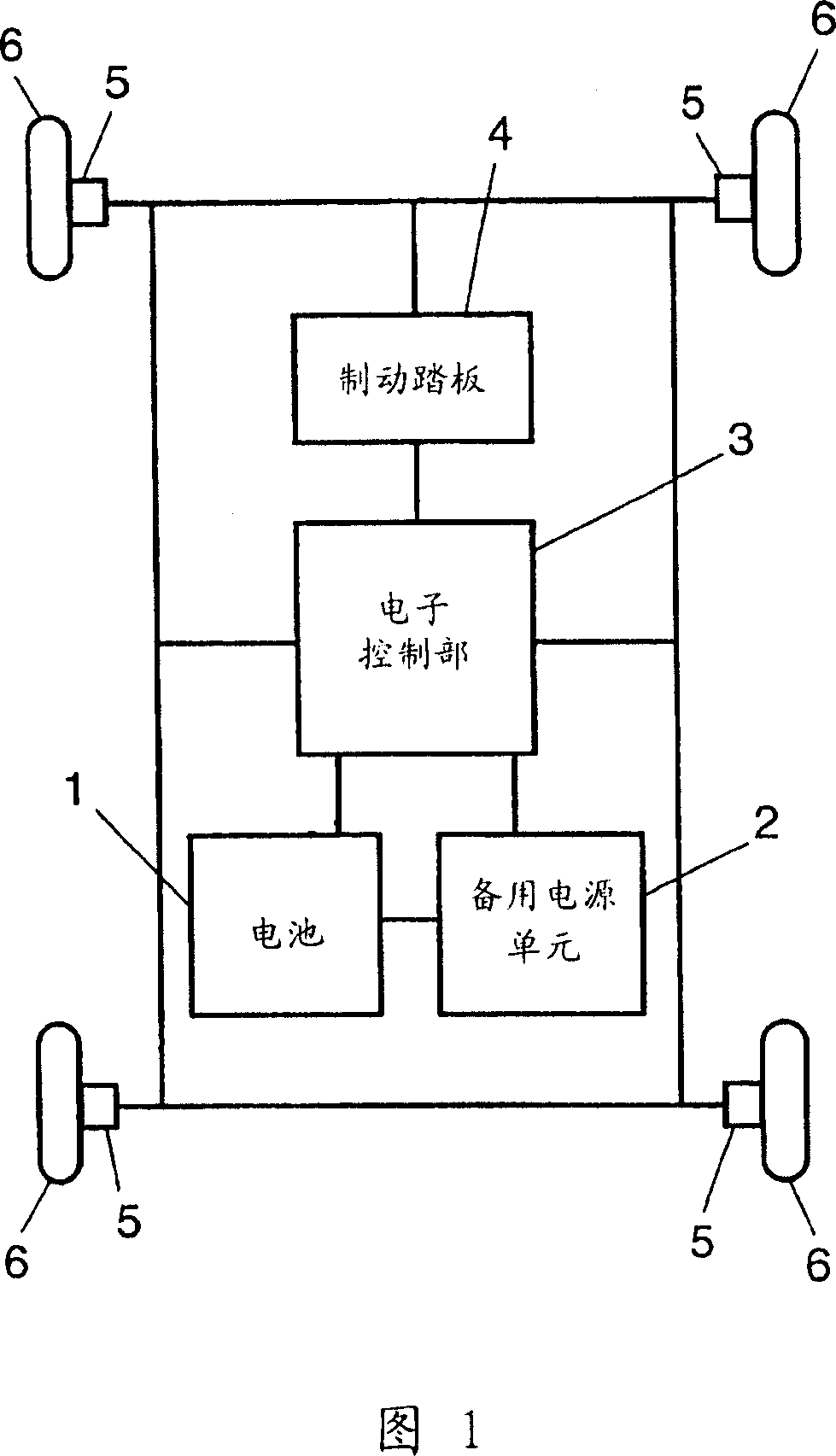
[0013] FIG. 1 is a configuration diagram of a power supply device for a vehicle according to an embodiment of the present invention.

[0014] In FIG. 1 , a 12V battery 1 supplies electric power to the vehicle. A backup power supply unit 2 is provided as an auxiliary power supply for the battery 1 . Furthermore, an electronic control unit 3 that outputs information for controlling braking of the vehicle is provided. Electric power is supplied to the electronic control unit 3 from both the battery 1 and the backup power supply unit 2 . In addition, a brake pedal 4 for transmitting information to control the braking of the vehicle to the electronic control unit 3 is provided. The electronic control unit 3 controls the brake 5 based on the information from the brake pedal 4 . The tires 6 are braked by the brakes 5 .

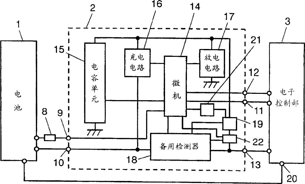
[0015] Next, the detailed structure of the vehicle ...


PUM


Abstract

A power supply device for vehicles is disclosed, which device includes a backup unit to the power supply as an auxiliary power supply employing a capacitor unit formed of plural capacitors. The auxiliary power supply includes a power supply section allowing the capacitor unit to power an electronic controller, and a compulsory operating section for operating the power supply section. An operating status of the power supply section is monitored even when a battery operates normally, so that the power supply device for vehicles with higher reliability and improved safety is obtainable.

Description

technical field [0001] The present invention relates to a vehicle power supply device mounted on vehicles such as hybrid vehicles and electric vehicles. In particular, it relates to a power supply device for a vehicle used in an electrically braked vehicle. Background technique [0002] In recent years, research and development of hybrid vehicles or electric vehicles is being accelerated. For this reason, various proposals have been disclosed in terms of vehicle braking, that is, development from conventional mechanical brakes to electric brakes is being accelerated. [0003] Generally, in order to control a vehicle electrically, a battery is used as its power source. At this time, only on the battery, when electric power cannot be supplied from the battery for any reason, control of the vehicle cannot be performed. Therefore, in addition to this battery, an auxiliary battery is also installed as an auxiliary power source so that it can cope with abnormal situations. [...

Claims


Application Information

Patent Timeline
Patent Type & Authority Applications(China)
IPC IPC(8): B60R16/033B60R16/02B60R16/03B60R16/04B60T1/10B60T17/18B60T17/22H02J7/00H02J7/14H02J7/34H02J9/06
CPCB60T17/22Y02T10/7022H02J7/345B60T1/10B60R16/03H02J9/062Y02T10/7005H02J7/1423H02J2310/46Y02T10/70
Inventor 三谷庸介大桥敏彦
Owner PANASONIC CORP
Why Eureka
Try Eureka