Magnetic core component, magnetic element, and production method for magnetic core component

A manufacturing method and magnetic technology, applied in the direction of magnetic core/yoke, inductor/transformer/magnet manufacturing, magnetic objects, etc., can solve the problem of large particle size distribution changes, poor plastic deformation of amorphous powder, and inability to press powder density to increase magnetic permeability Ratio amorphous powder magnetic core and other problems, to achieve the effect of increasing density and relative permeability, cheap and durable life

Inactive Publication Date: 2016-11-23
NTN CORP
View PDF9 Cites 8 Cited by
  • Summary
  • Abstract
  • Description
  • Claims
  • Application Information

AI Technical Summary

Problems solved by technology

[0010] If the soft magnetic composite powder described in Patent Document 3 is used, and the insulating coating-treated amorphous powder with an average particle size of about 50 μm and a particle size distribution on the normal distribution is used for powder compaction, even if the molding pressure is increased, the density will remain constant. The degree increases, but the plastic deformation of amorphous powder is poor, so it is difficult to obtain high-density products
Therefore, although the relative permeability of the amorphous powder itself is very high, as high as hundreds of thousands, there is a problem that the relative permeability of the dust core will stop at about 50
[0011] When two types of soft magnetic powders having different particle diameters described in Patent Document 4 are mixed, a certain degree of improvement in compacted powder density can be observed, but the effect of improvement is not sufficient for the following reasons.
[0012] If there are fine particles of amorphous powder, they will intrude into the clearance of the molding die during powder compaction, which will cause molding failures such as die breakage
In addition, if it is a mixed powder of powders with different average particle diameters, it is difficult to maintain the particle size distribution state during the flow of the powder and transport it directly. Therefore, there is a problem that the particle size distribution changes greatly from the hopper to the time before it is put into the mold. Amorphous powder cores that can increase the powder density and increase the magnetic permeability cannot be obtained

Method used


Image

  • Magnetic core component, magnetic element, and production method for magnetic core component
  • Magnetic core component, magnetic element, and production method for magnetic core component
  • Magnetic core component, magnetic element, and production method for magnetic core component

Examples


Embodiment 1

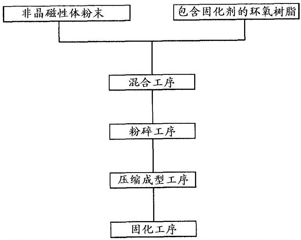
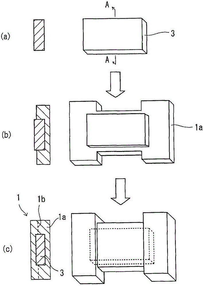
[0090] The particle size is below 150μm and the median diameter D 50 1940 g of 50 μm amorphous metal magnetic powder (Fe—Si—B based amorphous metal) and 60 g of epoxy resin powder containing dicyandiamide as a curing agent were mixed at room temperature for 10 minutes with a blender. This mixture was put into a kneader and heated and kneaded at 110° C. for 12 minutes. The compounding ratio of the amorphous metal magnetic powder was 97% by mass. The cake agglomerated by the kneader was taken out and cooled, and then pulverized by a pulverizer to obtain a powder that passed through a 60-mesh sieve. Then use the mold at room temperature at 2t / cm 2 Compression molding is carried out under the molding pressure. The compression-molded product was taken out from the mold, and thermally cured at 180° C. in air for 1 hour to manufacture a flat cylindrical magnetic core member with an inner diameter of 20 mm, an outer diameter of 30 mm, and a height of 5 mm. The magnetic core member...

Embodiment 2

[0095] When the magnetic core member is made into a compression-molded product using the powder obtained from the amorphous metal magnetic powder and the epoxy resin powder obtained from the amorphous metal magnetic powder and the epoxy resin powder that passed through a 60-mesh sieve, except that the molding condition is set at a temperature of 110 ℃, time 5 minutes, in the same manner as in Example 1, under the condition of 180 ℃ of temperature in the air atmosphere for 1 hour, carry out thermosetting, thereby make the flat circle of inner diameter 20mm, outer diameter 30mm, height 5mm A cylindrical magnetic core member. The density of the magnetic core part is 5.17g / cm 3 .

[0096] The magnetic properties and mechanical properties of the obtained magnetic core member were measured in the same manner as in Example 1. show the result in Figure 4 ~ Figure 6 .

Embodiment 3

[0098] 1940 g of an amorphous metal magnetic powder having a particle size distribution having a particle size distribution of 300 μm or less added with fine powder as an amorphous metal magnetic powder, and 60 g of an epoxy resin powder containing dicyandiamide as a curing agent are used in a blender Mix for 10 minutes at room temperature. This mixture was put into a kneader and heated and kneaded at 110° C. for 12 minutes. The cake obtained by agglomeration in the kneader was taken out, cooled, and pulverized by a pulverizer to obtain a powder that passed through a 28-mesh sieve. Then use the mold at room temperature at 2t / cm 2 Compression molding is carried out under the molding pressure. The compression molded product was taken out from the mold, and thermally cured at 180° C. for 1 hour in an air atmosphere to manufacture a flat cylindrical magnetic core member with an inner diameter of 20 mm, an outer diameter of 30 mm, and a height of 5 mm. The magnetic core member h...


PUM

PropertyMeasurementUnit
particle diameteraaaaaaaaaa
particle sizeaaaaaaaaaa
particle diameteraaaaaaaaaa

Abstract

Provided is a magnetic core component wherein: no faults such as cracks occur, even if same contains at least 90% by mass amorphous metal powder; and sufficient mechanical strength can be obtained. The magnetic core component comprises at least one magnetic powder, selected from simple amorphous metal powder and an amorphous metal powder covered by an insulating material, and a heat curable binder resin that have been heat cured and molded; and is characterized by containing 90%-99% by mass magnetic powder, relative to the total magnetic powder and heat curable binder resin content.

Description

technical field [0001] The present invention relates to a magnetic core member, a magnetic element, and a method of manufacturing the magnetic core member for electrical or electronic equipment such as inductors, transformers, antennas (rod antennas), choke coils, filters, and sensors. Background technique [0002] In recent years, with the development of miniaturization, higher frequency, and higher current of electric and electronic equipment, the same response has been demanded for magnetic core components. However, in the current mainstream ferrite materials, the material properties themselves have reached their limits, and new magnetic core materials are being explored. For example, ferrite materials are gradually being replaced by compressive magnetic materials such as sendust, amorphous metals, amorphous foils, and the like. However, the above-mentioned compressed magnetic material has poor formability and low mechanical strength after firing. In addition, the above...

Claims


Application Information

Patent Timeline
Patent Type & Authority Applications(China)
IPC IPC(8): H01F1/153B22F1/00B22F3/00H01F1/24H01F27/24H01F27/255H01F41/02C22C38/00C22C45/02B22F1/08B22F1/16
CPCC22C38/00C22C45/02H01F1/24C22C33/00C22C33/02H01F1/15383H01F41/0246B22F3/006C22C2202/02H01F3/08B22F2998/10B22F2999/00B22F1/16B22F1/08C22C45/08B22F1/052B22F2003/023B22F1/05B22F1/103B22F1/142B22F3/02B22F2207/13B22F1/147H01F27/255H01F27/2823
Inventor 森夏比古野田浩行岛津英一郎山下信好神户祥吾小田贵之宫崎真二
Owner NTN CORP
Why Eureka
Try Eureka