Diaphragm valves

Active Publication Date: 2006-07-04
CKD
View PDF6 Cites 8 Cited by
  • Summary
  • Abstract
  • Description
  • Claims
  • Application Information

AI Technical Summary

Benefits of technology

[0020]In the diaphragm valve of the invention, furthermore, the first and second diaphragms are placed in the valve chamber and the suck-back chamber respectively so that each diaphragm is curved outwardly. It is therefore possible to prevent crushing of a film portion of each diaphragm by the pressure of the liquid allowed to flow in the passage in the valve body. As a result, the durability of the second diaphragm can be increased. The diaphragm valve does not need frequent rep

Problems solved by technology

In diaphragm valves, generally, the motion of a diaphragm causes changes in volume on a downstream side of the diaphragm, which may lead to inappropriate draw-back and push-out of the liquid at valve opening and closing times respectively.
However, the conventional diaphragm valve 100 shown in FIGS. 5 and 6 has a problem that it could perform the suck-back function in theory but not sufficiently in practice because the diaphragm 117 constructed as shown tends to be distorted or warped by the flui

Method used


Image

  • Diaphragm valves
  • Diaphragm valves
  • Diaphragm valves

Examples


Example

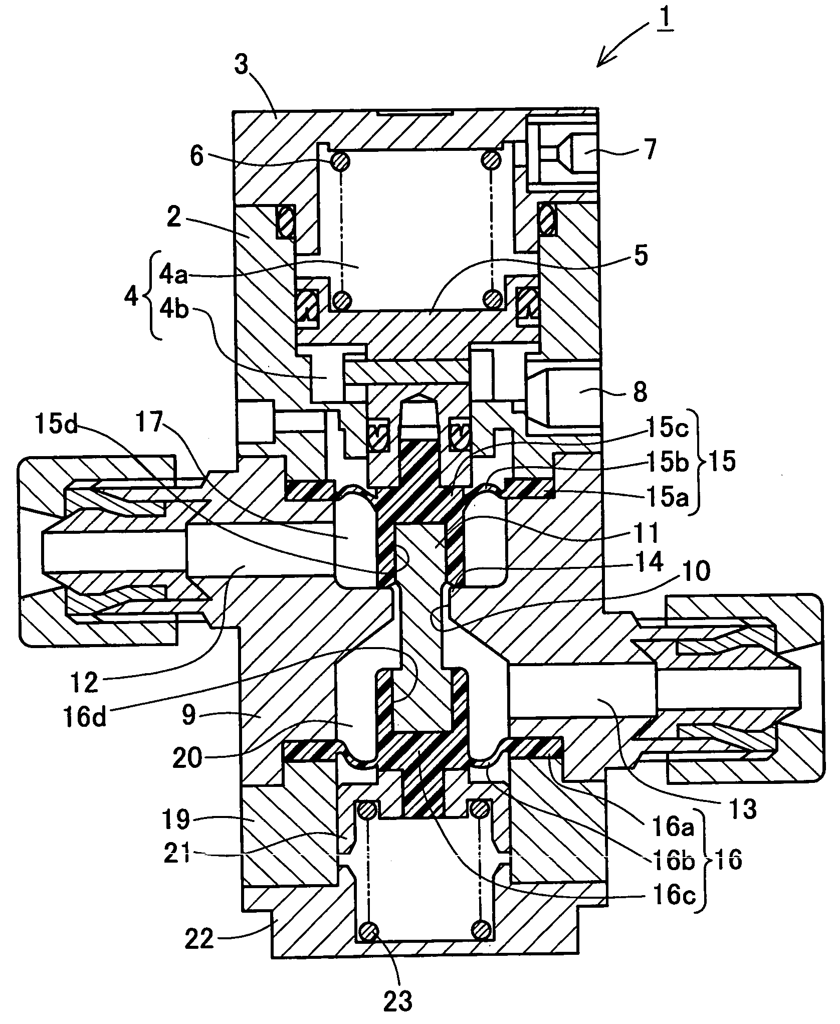
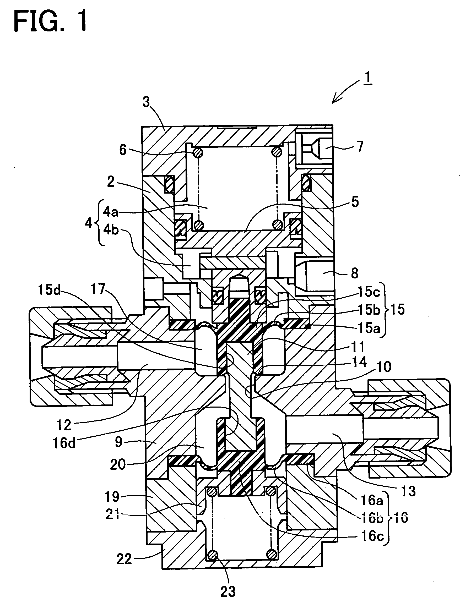
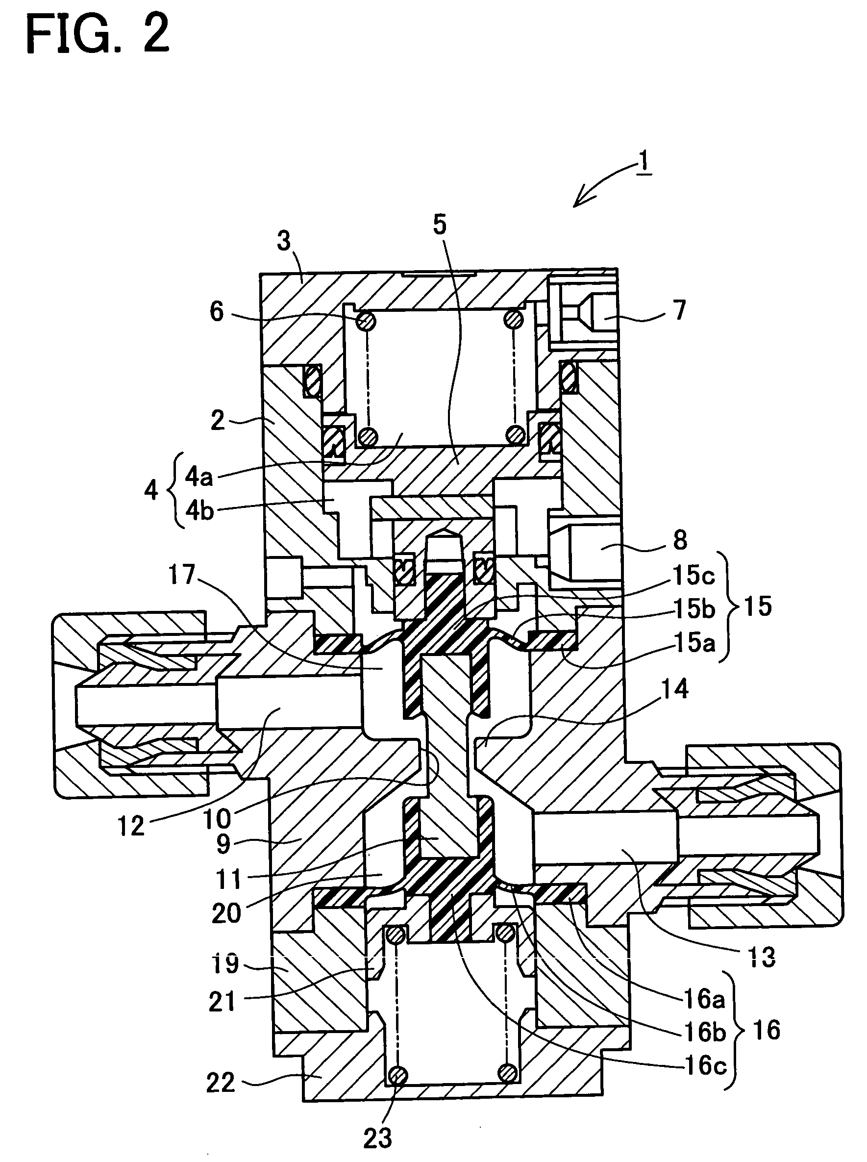
[0030]A detailed description of a preferred embodiment of a diaphragm valve embodying the present invention will now be given referring to the accompanying drawings. FIG. 1 is a sectional view of a diaphragm valve 1 in a closed state in the present embodiment. FIG. 2 is a sectional view of the diaphragm valve 1 in an open state. This diaphragm valve 1 is incorporated in for example a semiconductor manufacturing device and used as a chemical solution control valve which controls discharge of a chemical solution to be applied to semiconductor wafers.

[0031]The diaphragm valve 1 includes a piston cylinder assembly serving as an actuator for operating opening and closing of the valve by air pressure. In particular, the diaphragm valve 1 has a suck-back function to prevent a liquid from dripping out of a nozzle tip when the valve 1 is closed to stop discharge of the chemical solution.

[0032]The diaphragm valve 1 in the present embodiment is mainly constructed of a valve part in which a liq...


PUM


Abstract

A diaphragm valve capable of increasing durability of a diaphragm comprises a valve body internally formed with a valve chamber having an open upper end and a suck-back chamber having an open lower end, between an inlet passage and an outlet passage, and a through hole which provides communication between the valve chamber and the suck-back chamber. The open end of the valve chamber is closed by a first diaphragm which is brought into and out of contact with a valve seat. The open end of the suck-back chamber is closed by a second diaphragm. The first and second diaphragms are substantially identical in shape. Each circumferential edge portion of the first and second diaphragms is tightly retained by a retaining member mountable to the valve body so that the diaphragms are curved outwardly with respect to the valve chamber and the suck-back chamber respectively. The first and second diaphragms are connected by a connecting rod passing through the through hole so that the diaphragms are deformed synchronously by operation of an actuator.

Description

BACKGROUND OF THE INVENTION[0001]1. Field of the Invention[0002]The present invention relates to a diaphragm valve having a suck-back function.[0003]2. Description of Related Art[0004]In semiconductor manufacturing processes, conventionally, a predetermined amount of chemical solution are applied to semiconductor wafers to coat each wafer surface with a thin film. Recently, a micro fabrication technique in the semiconductor manufacturing processes has been promoted. Under the circumstances, need arises to exactly control the amount of chemical solution to be applied in order to form the thin film of even thickness. In a semiconductor manufacturing device, correspondingly, a diaphragm valve provided with a suck-back function has been proposed to prevent dripping of the chemical solution from a nozzle tip when supply of the chemical solution is stopped. FIGS. 5 and 6 are schematic sectional views of a diaphragm valve disclosed in Japanese patent unexamined publication No. 2003-185053....

Claims


Application Information

Patent Timeline
IPC IPC(8): F16K31/143F16K7/17F16K31/126F16K41/12
CPCF16K31/1268F16K31/1266
Inventor IJICHI, EITAROOSUGI, SHIGERU
Owner CKD
Why Eureka
Try Eureka