
Bumper back beam for vehicle

Inactive Publication Date: 2014-07-10
JEONG & DEOK
View PDF8 Cites 8 Cited by
  • Summary
  • Abstract
  • Description
  • Claims
  • Application Information

AI Technical Summary

Benefits of technology

The present invention aims to provide a bumper back beam for a vehicle that can prevent damage or deformation to the impact part and side members in the opening direction of the side members, and increase durability and final impact allowance.

Problems solved by technology

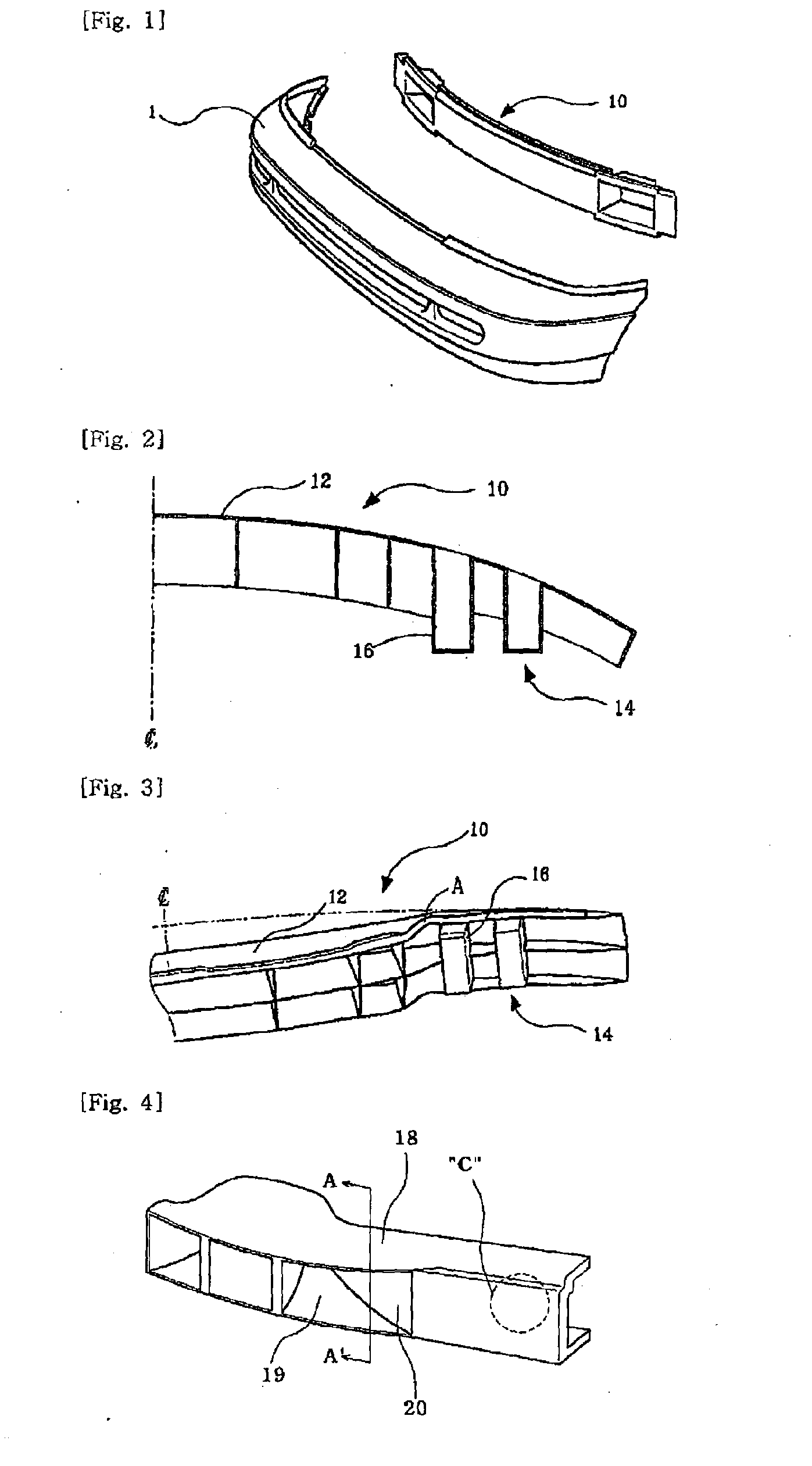
A bumper which is provided with the towers 14 having such vertical side surfaces has a problem that the bumper should be entirely changed with a new one even at a weak collision since the towers and reinforcement structures have serious deformation by the force which is transmitted in a front or side collision as shown in portion A of FIG. 3, and the deformation is permanent.
However, generated deformation cannot be appropriately absorbed due to the strengthened connection parts and parts C of the main body are likely to break when an impact of a predetermined level or higher is applied.
Therefore, there is still a problem that collision energy which is absorbed by the bumper is not high enough due to the breaking.
Further, the end portions of the upper plate and the lower plate press a bumper cover so that the bumper cover is likely to be damaged, and the end portions of the upper plate and the lower plate are bent so that a part of the reinforcement member is damaged in a collision in the prior art bumper.
However, there are still problems that, even though the rigidity itself of a bumper reinforcement member may be improved through the various change in shape and structures, the tower parts and the side members on which the tower parts are mounted are largely damaged in the mounted state thereof if a strong impact is transmitted through the front impact part in a collision.
That is, if a strong impact is transmitted through the central impact part, the direction of the impact is changed in a direction that the side members at both sides are open such that the side members are largely damaged in the process of such opening.
Further, the impact parts which are mounted on the side members are largely damaged or deformed in the opening direction.

Method used


Image

  • Bumper back beam for vehicle
  • Bumper back beam for vehicle
  • Bumper back beam for vehicle

Examples


first embodiment

[0069]The impact part 50 of the present invention is repetitively formed to have an outside space 56 which is open forwards, that is, towards a bumper and an inner space 55 which is open towards the opposite inside, as shown in FIG. 13 which shows a

[0070]A stiffener 80 is received in the inner space 55.

[0071]The stiffener 80 is made from a steel material or an aluminum material or a synthetic resin material having excellent strength, wherein the stiffener 80 is formed with a relatively small curvature R1 rather than that of the back beam 100, which has no curve, in the state that the stiffener 80 is positioned in the inner space 55. Further, clearances S are formed at both sides of the stiffener 80 between the inner space 55 and the stiffener 80 in the state that the center of the stiffener 80 is in contact with the center portion of the inner space 55.

[0072]At this time, the stiffener 80 is formed with a plurality of protruding ribs for filling the clearances S so as to further rei...

second embodiment

[0087]Further, in the present invention, one or more reinforcement bars 88 may be fixed to the both end portions of the stiffener 80 so as to connect the both end portions of the stiffener 80 by crossing the both end portions of the stiffener 80.

[0088]Therefore, the capacity for absorbing impacts is improved and the strength increases so that the weight of a product can be further reduced with reference to the same allowable strength and deformation can be reduced.

[0089]And, the size of the small curvature R1 of the stiffener 80 can be changed depending on the strength required for a bumper reinforcement member, wherein the radius is decreased if the required strength is increased while the radius is increased if the required strength is decreased.

[0090]FIG. 18 to FIG. 25 show the second embodiment of the present invention.

[0091]The vehicle back beam 100 of the present invention forms a closed section in the shape of a rectangle which is long in the vertical direction as shown in FI...


PUM


Abstract

A bumper back beam for a vehicle includes an impact part positioned in a center portion, and tower parts formed at rear portions of both sides of the impact part so as to be fixed to crush boxes on the front ends of side members of a vehicle body, and is characterized in that the impact part is formed such that the section of the impact part has an inner space which is open towards the opposite inside portions of a bumper, and a stiffener is received in the inner space, wherein the inner space and the stiffener are formed with a curvature which is smaller than that of the back beam such that clearances are formed at both sides between the inner space and the stiffener. The bumper back beam improves impact resistance and maintains appropriate deformation while preventing damage to the side members, when a bumper is impacted.

Description

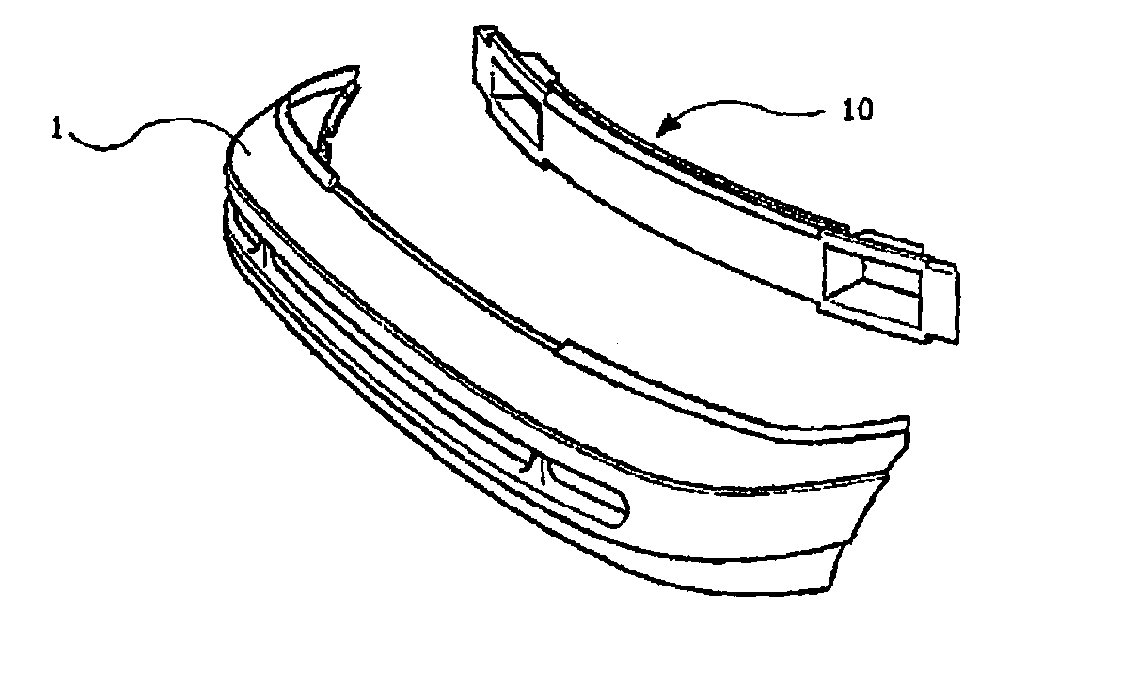
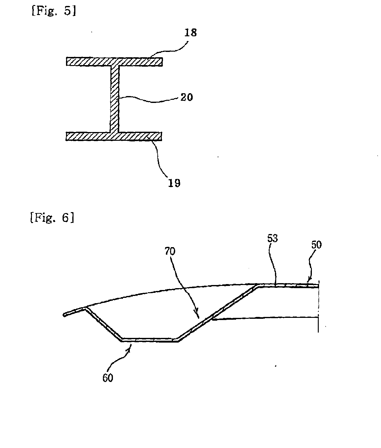
TECHNICAL FIELD[0001]The present invention relates to a bumper back beam for a vehicle and, more particularly, to a bumper back beam for a vehicle, wherein a stiffener is inserted into a back beam, which is made from a synthetic resin material and connects side members, and the back beam and the stiffener are formed in different curvatures from each other such that impact resistance can be improved and appropriate deformation is maintained while preventing damage to the side members when an impact is applied to the bumper.DESCRIPTION OF THE PRIOR ART[0002]In general, a bumper reinforcement member for a vehicle is mounted on the rear portion of the bumper of a vehicle so as to relieve an impact in a collision.[0003]FIG. 1 is a perspective view of a bumper 1 for a vehicle and a bumper reinforcement member 10 for a vehicle, which are in a disassembled state. As shown in FIG. 1, the bumper reinforcement member 10 for a vehicle is mounted on the rear portion of the bumper 1 so as to reli...

Claims


Application Information

Patent Timeline
IPC IPC(8): B60R19/18
CPCB60R19/18B60R2019/1853B60R2019/1866
Inventor JEONG, UN DEOKSUNG, JOON YUB
Owner JEONG & DEOK
Learn More